


[087] Real World Magnetics Design Issues
Many things can go wrong in the design and production of power supply magnetics.
Introduction
Proper design of magnetics components is at the heart of any power converter. In this article, the flaws of some production magnetics are shown, clearly showing why it is essential that designers of power supplies should be intimately involved in magnetics design and characterization.
Teaching Power Magnetics Design
In the world of power supply design, engineering students at universities are not taught practical magnetics design and fabrication. Very little formal education is offered in this area, and good magnetics design tips from industry experts can be hard to find [1]. In our design workshops, we spend a full two days on magnetics design, optimization, winding, and testing in order to help attendees become more well-rounded engineers [2]. This allows them to develop their own prototypes, improve designs, and properly specify their magnetics components to magnetics manufacturers.
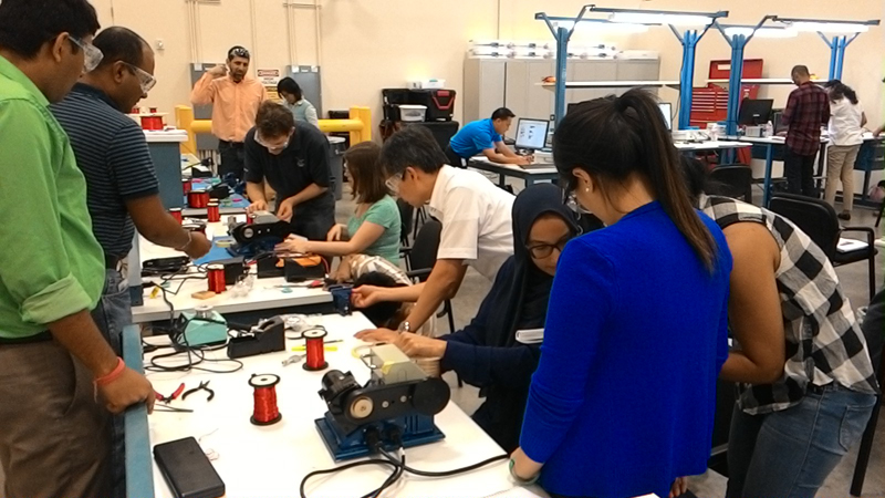
Figure 1: Enthusiastic Workshop Students Winding Transformers
Trusting Design to Magnetics Vendors
Engineers who are new to magnetics often feel that the design or transformers and inductors should be placed in the hands of the magnetics vendors who surely know more about building the components than they do. However, this is not always the case, as we will see from the following examples. Numerous things can go wrong with purchased components, and vigilance is always needed to ensure that magnetics components are suitable for production. Very often, common sense just needs to be applied.
Figure 2 shows a flyback transformer with a ferrite core. If you look carefully at the outer legs of the core, a small piece of gapping material is visible on the right hand side. The core has only been gapped on the one side. This means that the two core halves meet on the left pole piece in a line contact. Two problems arise from this mechanical arrangement. First, when current starts to flow in the transformer, the edge contact of the core will saturate, progressively increasing as higher current flows. Secondly, and more severely, the line contact will be mechanically stressed and is very likely to fracture with shock and vibration. Experienced magnetics manufacturers would never build a transformer this way, but lower cost vendors are often unaware that this is not acceptable.
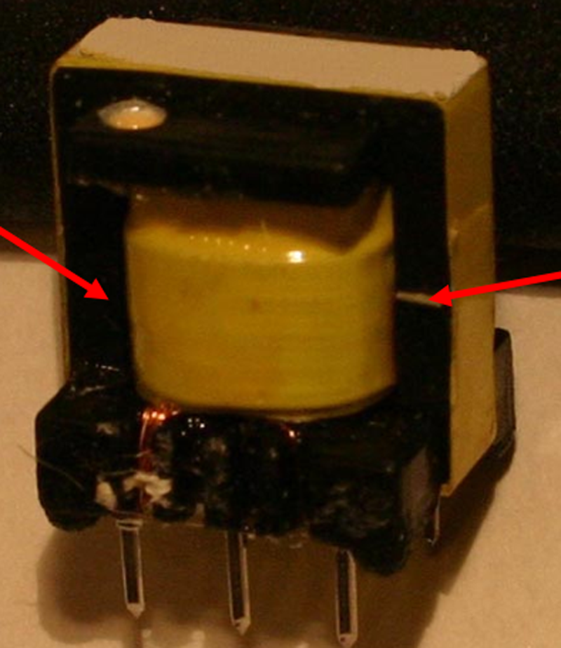
Figure 2: Asymmetrically Gapped Core
Figure 3 shows inductor current waveforms for a buck converter. The inductor is an off-the-shelf design rated at 9 A. However, even with only 5 A current, the inductor core very quickly heats up, and starts saturating after about 30 seconds as shown in the middle waveform. After 1 minute, harder saturation occurs, and the wire insulation eventually is burned off leading to total failure. Off-the-shelf parts are often aggressively marketed and rated beyond where they are supposed to be used, and great care must be paid to thermal testing such parts if they are to be used in a design.
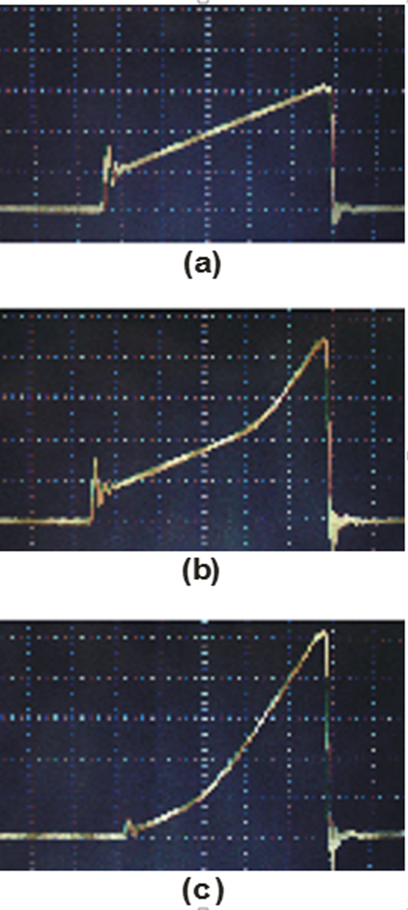
Figure 3: Progressive Saturation of an Off-the-Shelf Inductor
Figure 4 shows a commercial inductor wound on a drum core. Many turns are used, but the winding arrangement is far from optimal. The final turn of the inductor crosses over the initial turn, touching it very close to the area where the soldering process has stripped back the insulation. This leads to two problems. Firstly, there is a risk of insulation failure with two adjacent windings that may have high voltage applied to them with time, heat, and vibration/shock (the inductor was intended for a 400 V application). Secondly, the resonant frequency is lower than if the start and stop wires are kept away from each other.
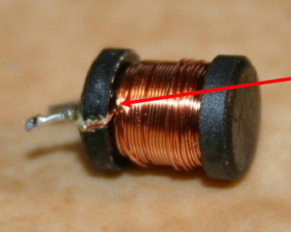
Figure 4: Inductor with Start and Stop Leads Crossing
Figure 5 shows a flyback transformer with improper arrangement of winding terminations. Two adjacent wires have very little spacing in the region where the insulation has been completely removed. The voltage differential is over 200 V, and the separation of the windings is less than 0.5 mm. Shock and vibration, or changes in assembly tolerance, can easily cause the two wires to touch each other, causing failure of the power supply.
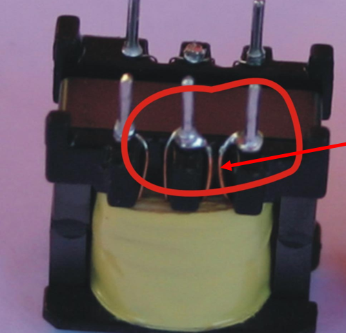
Figure 5: Insufficient Spacing Between High-Voltage Windings
Figure 6 shows a danger of using solderable triple-insulated wire. The termination of the wire has been heated too long, and the insulation has been removed all the way up into the transformer winding area, making the transformer unsafe. If solderable insulation systems are to be used for safety, the manufacturing process must be very carefully supervised.

Figure 6: Removal of Triple Insulation with Too Much Heat
Figure 7 shows saturation in a transformer during startup of a flyback converter. The transformer is inadequately designed for the control parameters of the chip, and peak stresses are over 5 times higher than the circuit was designed for. The value of the inductor at the peak current is less than 5% of the initial inductance. Saturation of magnets is an increasingly common event in modern design and this a significant contributor to the poor lifetime and reliability of many commercial products.
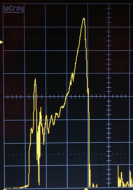
Figure 7: Flyback Primary Current Waveform Showing Saturation.
Summary
Magnetics are the most crucial component at the heart of power converters. They should be properly designed, specified, and tested. The power supply engineer should be intimately involved in every aspect of the magnetics design and should not blindly trust the magnetics vendors to the job for them. There is a very close relationship between the details of the magnetics and the waveforms that are seen on the bench. Proper design and specification will greatly facilitate better efficiency, reduced component stress, and reliability. Only the power supply engineer is qualified to make sure that the magnetics are working properly. Real-world practical training is a key part of this process.
References
“Power Supply Cookbook”, a Handbook for Practical Design of Power Supplies and Magnetics by Marty Brown, https://pwrelectronic.files.wordpress.com/2010/06/power-supply-cookbook.pdf. (Download endorsed by Marty Brown.)
Magnetics and control hands-on training, http://www.ridleyengineering.com/workshops.html
AP300 Application Notes for Magnetics Measurements, http://www.ridleyengineering.com/analyzer.html
Join our LinkedIn group titled “Power Supply Design Center”. Noncommercial site with over 7000 helpful members with lots of theoretical and practical experience.