


[031] Choosing the Inductor for a Buck Converter
How to select the size of the inductor for a buck converter.
Introduction
In this article, Dr. Ridley examines how the value of a buck inductor should be selected. A supposedly simple process can turn out to be much more complicated than expected, and the range of allowable inductors is found to be quite large.
Design Rules for Choosing the Inductor
Five or six times a year, I teach a class in power supply design to 30 working engineers. One of the design examples involves a buck converter, and the design starts with the choice of the inductor value. I always ask the students what value inductor should be used, or how much ripple current should be in the inductor. (Ripple current ratio is usually defined as the peak-to-peak value of the inductor current at high line, divided by the maximum load). Their answers typically vary, from a value of 10% up to perhaps 30%.
A traditional value of inductor current ripple is 10%, and you will find this in several books. Reference [1] uses this value as a starting point for design, but does suggest at the end of the article that the value can be changed depending on the desired output ripple. Further examination of literature shows a huge range of recommendations. References [1] to [13] suggest ranges from 2.5% to 50%.
References [14,15] select the inductor according to the minimum load, with the intent of keeping the converter always in continuous-conduction mode (CCM). This can lead to a very large inductor if the light load is very small.
Which one of these is the correct value? As is often the case in designing power supplies, there is no one correct answer, and it will always depend on the very specific converter that you are working on at the moment.
Where do the Rules come from?
We usually find in power electronics that design “rules-of-thumb” arise from some practical basis in reality. There are several different factors that drive the choice of inductor value.
1. Output Ripple Voltage – older output capacitor types tend to drive inductor values to a higher number. Modern innovations in capacitor design have driven the ESR down to very low values, and rarely is the output ripple the driving factor in choosing the inductor.
2. Inductor Loss – Higher ripple current leads to higher RMS current in the inductor, plus greater AC currents and higher proximity losses. Core losses will also increase with larger ripple current. A higher value of inductor, with low ripple, has higher dc conduction loss.
3. Switch Conduction Loss – the RMS current in the switch climbs with inductor current ripple.
4. Rectifier Conduction Loss – the RMS current in the rectifier climbs with inductor current ripple. This is an important factor when using a synchronous rectifier, but less important when using a diode.
5. CCM operation – References [14,15] choose the inductor to give a ripple which is twice the minimum load. This is to avoid DCM operation at light load. In the early days of power supply design, this was an important factor to keep good transient performance under all conditions. With a modern power supply, using current-mode control, there is no reason at all to keep the converter in CCM operation.
Buck Converter Design Example
Searching deeper into the literature than the short list included with this article will not lead you to any conclusions regarding the right value of inductance. For every converter design that you do, the proper answer will depend upon your very specific set of circumstances. And for each specific case, a detailed design must be completed and tested before coming to any conclusions about the right value.
For example, Figure 1 shows a specific design case. The switching frequency of the buck converter is 200 kHz, and the output specification is 5A at 12 V from a 18-36 V input. The output capacitor is preselected at 1000 µF with a 10 mΩ ESR. The choice of the output capacitor can be as wide ranging as the choice of the inductor value, and is not discussed in more detail in this article due to space constraints.
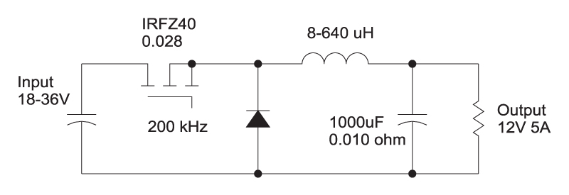
Figure 1: Buck Converter with Parameter Values
The ripple current in the converter is maximum at high line, and the value of the ripple is shown in figure 2 for an inductance of 160 µH which gives a current ripple ratio of 10%.
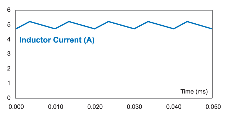
Figure 2: Inductor Current Waveforms 10% Ripple
The peak-to-peak value of the current is 0.5 A, and this results in a 5 mV ripple on the output of the converter. In most practical design cases, the output ripple at the switching frequency is not the main driver for inductor choice, since it is much lower than is needed. It is almost always far lower than the high-frequency switching noise on the output.
There nothing special about choosing the 10% ripple value for Figure 1. It is just one value in the range that could be used. For each value, we must optimize the design of the inductor before we can really assess the performance properly. This can be a time consuming process, but for this study, it was automated using the design software POWER 4-5-6 [18].
The inductor designed for this case had the following practical design constraints applied when assessing each value of inductor:
1. Magnetics Inc. RM8 core with R material was used.
2. Turns were set to the nearest integer value.
3. Maximum flux level was designed for 0.3 Tesla, with 10% overcurrent limiting.
4. Maximum wire size was 20 awg (0.9mm diameter) to limit mechanical stress on bobbin.
5. Multiple strands of wire, and multiple layers were used as appropriate.
6. Winding loss includes proximity loss as predicted by Dowell’s equations [16].
7. Core losses include advanced modeling techniques [17].
There are hundreds of cores that could have been chosen, but the RM8 was convenient and available. It will not necessarily be the optimal choice since the definition of “optimal” varies for every user.
Table I shows the results for designs, with a range of inductance from 640 µH down to 8 µH. This corresponds to a ripple ratio ranging from 2.5 % (as in the example of [11]) up to 200%, the boundary of discontinuous conduction mode at full load.
|
L(µH) |
RippleRatio |
Turns |
DCRΩ |
ACRΩ |
WindingLoss (W) |
CoreLoss (W) |
InductorLoss (W) |
FETLoss (W) |
TotalLoss (W) |
|
640 |
2.5 |
221 |
1.7 |
53.8 |
43 |
0 |
43 |
0.41 |
43.41 |
|
160 |
10 |
58 |
0.112 |
5.5 |
2.94 |
0 |
2.94 |
0.26 |
3.20 |
|
80 |
20 |
31 |
0.30 |
1.5 |
0.88 |
0.003 |
0.883 |
0.25 |
1.113 |
|
40 |
40 |
17 |
0.10 |
0.4 |
0.41 |
0.015 |
0.425 |
0.25 |
0.645 |
|
20
|
80
|
10
|
0.006
|
0.14
|
0.23
|
0.067
|
0.297
|
0.26
|
0.557
|
|
10 |
160 |
7 |
0.003 |
0.03 |
0.24 |
0.179 |
0.419 |
0.31 |
0.729 |
|
8 |
200 |
6 |
0.002 |
0.02 |
0.25 |
0.264 |
0.514 |
0.34 |
0.844 |
Table 1: Inductor and Switch Loss with Different Ripple Values Using RM8 Core
It is clear from the table that for this design case, with the chosen core size, the largest inductor was a very poor choice, with a loss of 43 W in the inductor windings. The 10% ripple case also has a higher dissipation than is desirable. The designs from 40% ripple to 200% ripple were all excellent.
It is interesting to see that the big change in ripple from 10% to 200% (20 times) only incurred a relatively small increase in conduction loss of the power FET. The increase in the RMS current value does not change as dramatically as one might expect.
Core losses were low for all designs, as would be expected when using a ferrite material. This allows the inductor to operate at high ripple current without a big penalty. (This would not be true for many of the lower-cost core materials found in the standard component designs.) Overall, the overall lowest loss value of inductor gave an 80% ripple ratio. The current waveform for this case is shown in Figure 3.

Figure 3: Inductor Current Waveforms 80% Ripple.
Summary
Choosing the proper value of an inductance can have a tremendous impact on the final size, cost, and efficiency of a buck converter. There is, however, no single specific value that is correct for all converters. The value of the inductor can be freely selected over a practical range from 10% to 200%. In every power supply, the specific constraints impacting the design choice will be unique, and the optimal value for the inductor must be found by trying multiple values and, ultimately, testing the designs in the circuit.
The design example given in this article had an optimal ripple of 80%. If I had to choose one specific number to get people started, I would agree with Reference [2] and begin with a ripple factor of 40%, but with the clear understanding that it is not a problem to move significantly away from this number, and the number should not be blindly accepted.
Other Recommendations
1. Jerry Foutz, “Switching-Mode Power Supply Design Tutorial Simple Switching Topologies”, http://www.smpstech.com/tutorial/t03top.htm start with10% ripple.
2. Sanjay Maniktala, “Switching Power Supplies A to Z”, 40% ripple.
Semiconductor Vendors
3. Micrel, “MIC4574 application note”, http://www.micrel.com/_PDF/mic4574.pdf, 10% ripple (Figure 3), 34% ripple(Figure 1).
4. GMOS Technology corporation, “GT1512 Datasheet”, 15% ripple.
5. Microchip, “MCP1612 Datasheet”, 16.5% ripple.
6.TPS4000 controller reference design”, 25% ripple.
7. Analogic, 30-40% ripple.
8. Sanjaya Maniktala, National Semiconductor, “Current Ripple Ratio Simplifies Selection of Off-the-Shelf Inductors for Buck Converters” http://powerelectronics.com/mag/power_current_ripple_ratio/, 25-50% ripple.
9. Maxim application note – 30% ripple.
10. National Semiconductor, “Selecting Inductors for Buck converters”, http://www.national.com/an/AN/AN-1197.pdf, 30-40% ripple.
Magnetic Component Vendors
11. Douglas R. Kokesh, Tyco Electronics Power Components, CoEv Magnetics Group, “Sizing; a Power Inductor - An aid to employment of switch mode power supplies”, http://www.designfax.net/archives/0304/0304power_inductor.asp, 2.5% ripple.
12. Coiltronics, 10-30% ripple.
13. GB International Custom cores, “Using GBI’s 4400 Series to Design Buck Regulators”, http://www.gbint.com/Files/Apps/General Apps/GB-4400-001.htm, 2 x minimum load.
14. Wurth Electronics, “Power Inductors 8 Design Tips”, 30% ripple.
15. Jim Holdahl and Terry VanConant, CoEv, “Demystifying Buck Inductors”, http://powerelectronics.com/mag/power_demystifying_buck_inductors, 2 times minimum load.
Magentics Design Example References
16. Ray Ridley, “Proximity Loss in Magnetics Windings”
17. Ray Ridley and Art Nace “Modeling Ferrite Core Losses”
18. Ridley Engineering, “Power 4-5-6 Simulation and Design Software”