


Testing
-
[004] HF Transformer Measurement and Modeling
How to measure and model high-frequency magnetics for switching power supplies. Essential steps for both custom-designed parts, or purchased components.
Power Supply Design Tips
This article points out some of the issues involved in designing, measuring, and modeling high-frequency magnetics for switching power supplies.
Despite efforts from some magnetics vendors to provide off-the-shelf components to power supply designers, almost all high-performance magnetics are custom. There are many deep and complex issues involved in the design of magnetics. I will try to cast some light on just a few of these issues.
Transformer Design Example
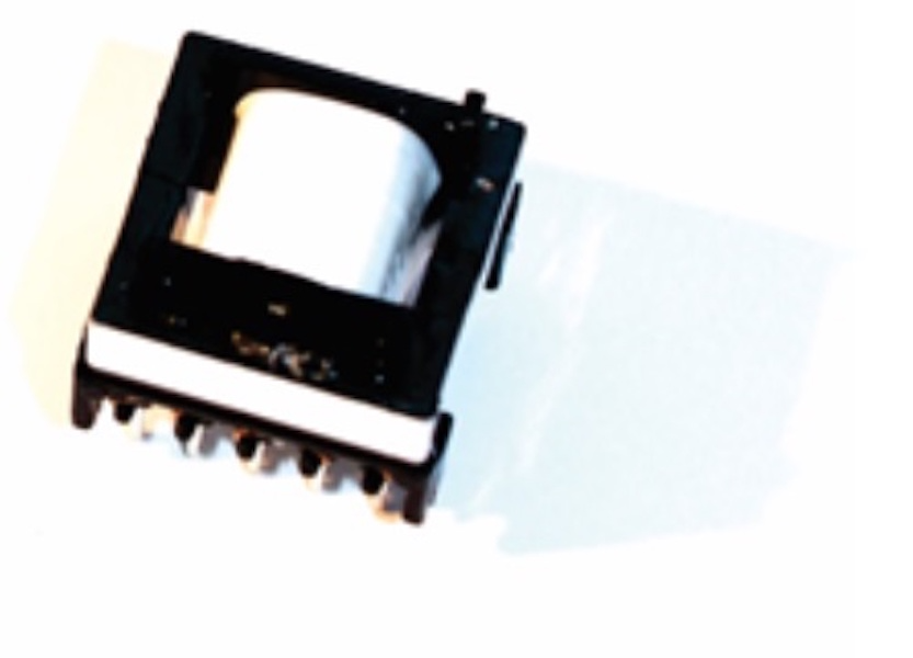
Figure 1 shows a simple 1:1 transformer. The transformer uses an ungapped EPC-25 core from TDK, made from PC-44 material. This transformer was designed for use in a 60 W forward converter with 36-60 V input and 12 V output.
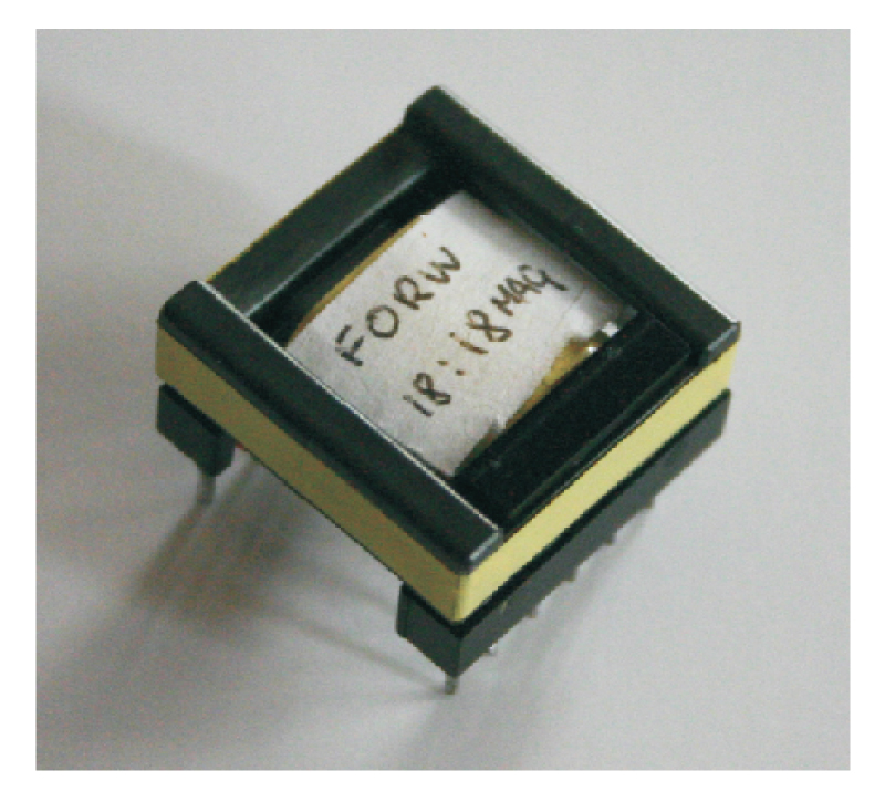
Figure 1: A simple 1:1 transformer designed for a 100 kHz, 60 W forward converter.
Figure 2 shows the winding layout, with just a single layer of 18 turns for the primary winding, a layer of thin insulation tape, and a single layer of 18 turns for the secondary winding.
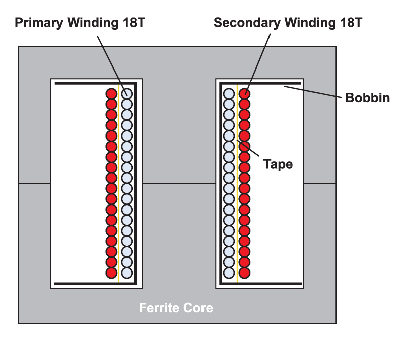
Figure 2: Winding layout of the transformer of Figure 1.
This is a very straightforward, easy-to-manufacture design of a two-winding transformer. However, as you will see below, the resulting circuit element created is anything but simple.
-
[005] High Frequency Power Inductor Design
Proximity Loss in Magnetics Windings
Exploring the use of custom versus off-the-shelf magnetics design. Standard parts are designed to a price point, and must be tested properly if you want to use them.
Power Supply Design Tips
In this article, we continue the theme of custom versus off-the-shelf magnetics design. The relatively simple output inductor of a forward converter is used as an example to show the issues and pitfalls involved in trying to use off-the-shelf inductor designs for high-frequency power supply applications.
Power Inductor Design
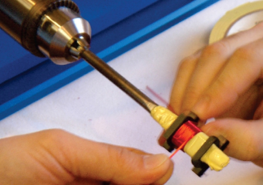
When I first started my career in power electronics, over 25 years ago, all magnetic components were custom designed and manufactured. In our current power supply design workshops, we dedicate an entire day to the theory and practice of making custom inductors for switching power supplies. Attendees at the course design, analyze, and build their own inductors and transformers in the lab.[1]
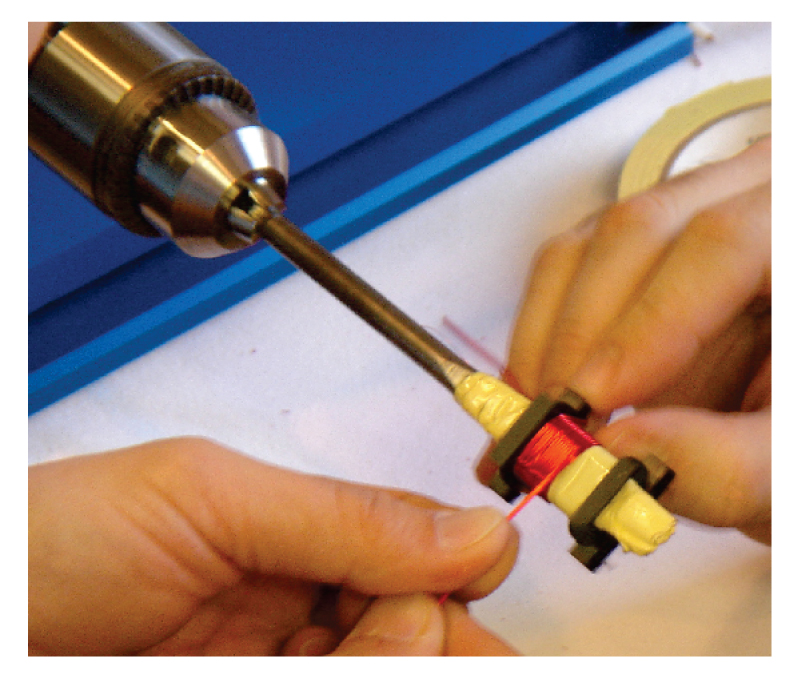
Figure 1: Building custom magnetics in our design workshop.
In the last few years, numerous companies have developed kits of standard parts aimed at the semiconductor companies to integrate into their designs. This proliferation of parts has recently led me to wonder if custom inductor design was becoming a skill belonging more to the past than the future.
Figure 2 shows two inductor designs, one developed in our workshop for a rugged 60-W converter, and the smaller low-cost, off-the-shelf part. You can see a significant size advantage of the standard component.
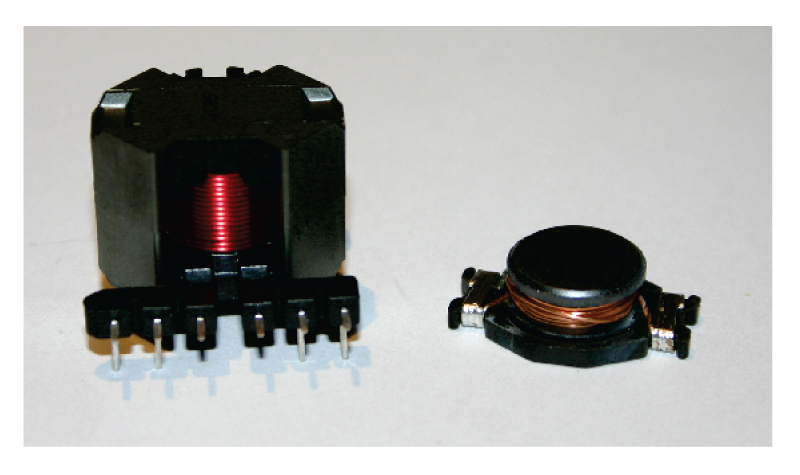
Figure 2: (a) 47 µH custom inductor and (b) off-the-shelf commodity component
The 47µH custom inductor was designed to operate continuously at 5 A, with plenty of margin for overcurrent situations.
The off-the-shelf inductor, also 47µH, had a single number assigned to it on the parts kit—a current rating of 5 A. Since the parts kit is aimed at the non-experienced power supply designer, it seems reasonable to assume that the inductor is suitable for a 5 A converter application
The parts are quite different in their design, as shown in Fig. 3. The custom-made inductor has a single-layer winding on an RM8 core, with a gapped center leg. The windings are a significant distance away from the center leg gap, essential to avoid proximity losses in the windings at high frequencies.
-
[006] The Digital Power Supply Revolution
Digital power is all the rage now, but don't expect it to shorten your design time, or to eliminate the need for complete optimization of the analog parts of the power supply.
Introduction
At the recent Applied Power Electronics Conference, digital power supplies were featured everywhere, in papers, seminars, and poster sessions. Applications were widespread, in VRMs, power factor correction circuits, inverters, and dc-dc converters.
It’s easy to start feeling overwhelmed with all this information on digital applications. And, in reading the material, to feel like you are perhaps missing the boat with your simple analog solutions. In this article, I’ll examine some of the issues and misconceptions about digital control.
Digital Control is New?
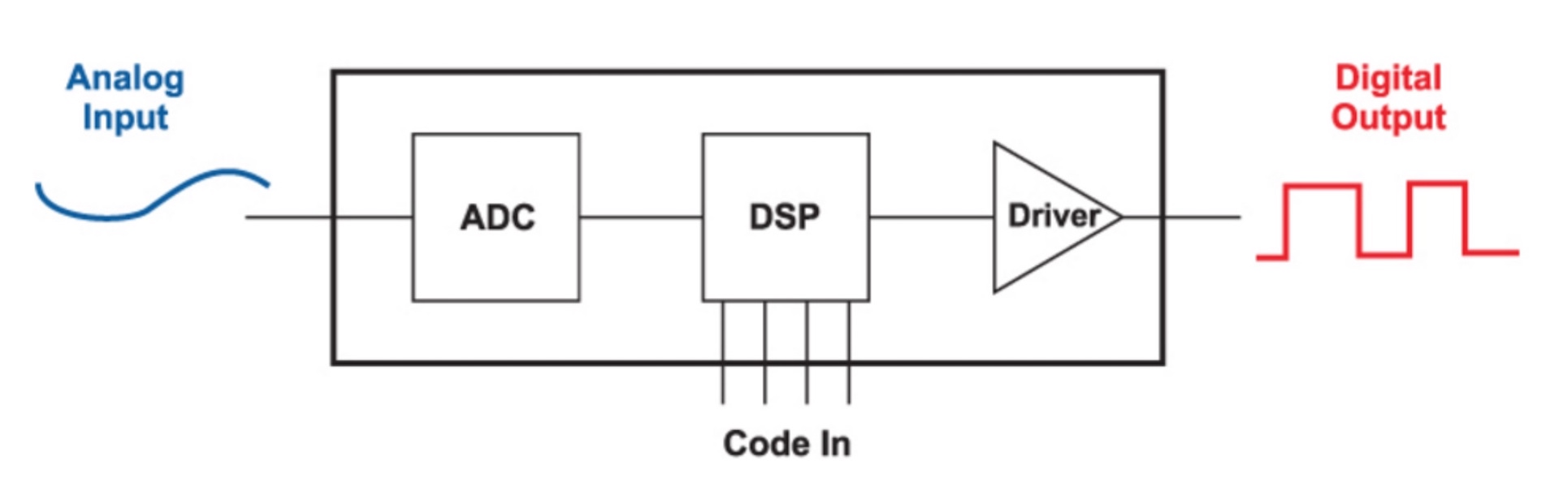
Figure 1 shows the block diagram of a digital controller. At the input side, an a/d converter samples an analog waveform of the power supply, and converts it to a digital value. The analog waveform may be the output voltage, or some pre-processed waveform where it has already been compared to a reference.
Sampling is done carefully, in an effort to avoid switching noise from affecting the results, and this simple sampling process can be quite complex, especially if there are multiple converters operating together in a system.
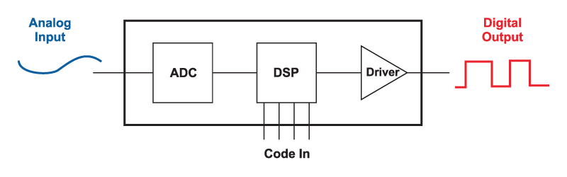
Figure 1: Block diagram of Digital Controller
The resulting digital signal then enters the processor of the digital controller, which sends the gate drive to the system. The driver circuitry may or may not be included in the controller, and this was discussed in the December 2006 issue of this magazine.
Much of the focus in recent years has been concentrated on solving the issues of the resolution of the digital output pulse. Numerous researchers have come up with solutions, including delay gates, to provide resolution beyond the clock frequency of the digital controller. This is important to avoid numerical oscillation.
Now let’s look at the so-called analog controller—yesterday’s technology if you listen to all the digital papers. Figure 2 shows a typical controller. The output voltage of a converter is processed with an analog amplifier, and discrete analog parts are used to compensate the feedback. The output of the error amplifier then is compared to a ramp with a comparator. The ramp also forms the clock of the converter.
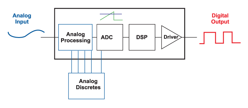
Figure 2: Block diagram of “Analog” Controller
The ramp-reference circuit is nothing more than a simple A-D converter, directly generating a digital waveform, and setting the width of the pulse at the output of the controller. If you look at the input and output waveforms of Figure 1 and Figure 2, one thing should be immediately obvious: the analog controller that we have used for over 20 years in this industry is, in fact, a digital controller!
It has all the features required—and ADC, digital processing circuitry, and digital output. It is also an incredibly elegant solution to the digital controller problem. The clock frequency does not need to be any higher than the desired switching frequency of the power supply, and yet the output digital pulse has infinite resolution. This is something the new digital controllers are still struggling to achieve.
It is very important to recognize that the controllers we’ve always used are digital controllers. It stops us from worrying about whether we are using the latest in technology—analog or digital—when in fact they are both digital with different implementations. And it moves us forward to consider what the real difference is between the old and new, and whether you need it.
The core difference is that the new controllers are programmed with software, whereas the old controllers are hard wired, and not as flexible. As we’ll see in this article, the capability to reprogram may not be as important as claimed for your converter.
-
[007] Capacitors for Switching Power Supplies
The changing characteristics of the capacitors used in power supplies are examined. They are not as simple as most engineers assume.
Introduction
In several past articles, we have examined some of the complex characteristics of the power magnetics of a switching power supply. In this article, we examine another major passive component of the power supply—the capacitor. This is often a component that is viewed as a simple part that doesn’t require too much attention.
In this article, we examine another major passive component of the power supply—the capacitor. This is often a component that is viewed as a simple part that doesn’t require too much attention.
Power Supply Capacitors
Figure 1 shows the simple buck converter. Given modern integrated controllers, the design task of the engineer is apparently very simple—all we have to do is select and inductor and two capacitors, and the job is done. The choice of inductors can become very complex, and now we’ll see how capacitors can be troublesome, too.
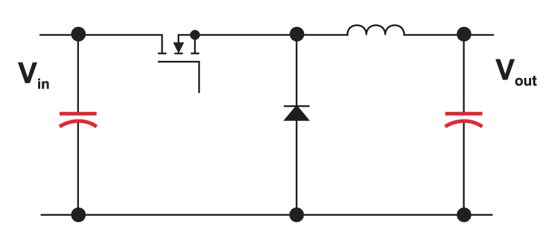
Figure 1: Buck converter with critical capacitor components. The output capacitor impedance determines the mid- and high-frequency response of the converter using either voltage-mode, current-mode, or any other form of control, including digital.
I’m often asked to perform worst-case analysis of switching power supply designs like this for companies. Step one of this process usually consists of the company sending me schematics, parts lists, and component data sheets. Before proceeding further, I always have to ask for working physical samples of the power supplies to test on the bench. To the alarm of people not familiar with power supplies, much of the worst-case analysis depends on measurements of existing designs, combined with documented datasheet variations which will shift the design.
Component data sheets are rarely adequate for properly characterizing parts, and a comprehensive analysis requires information either not readily available from manufacturers. Additional measurements are needed for magnetics, and additional measurements are needed for capacitors, too.
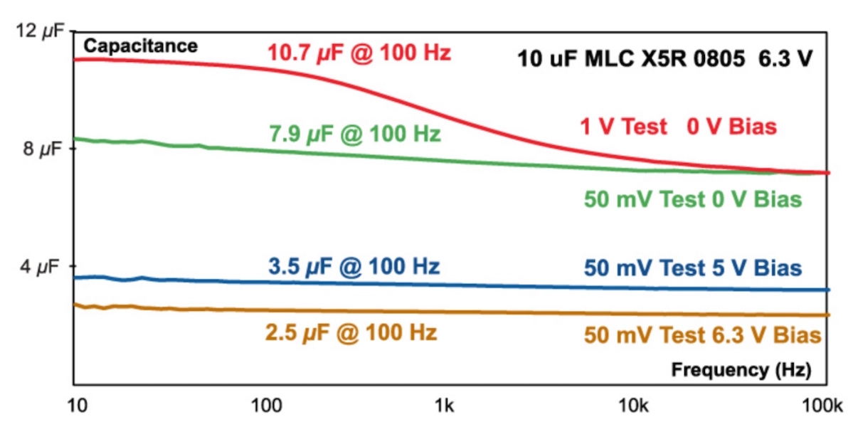
Low-Impedance Capacitor Measurement
A simple fixed RLC tester with a single measurement frequency is not adequate for characterizing capacitors for use in a modern switching power supply. The capacitors must be measured over a wide range of frequency to fully characterize their behavior.
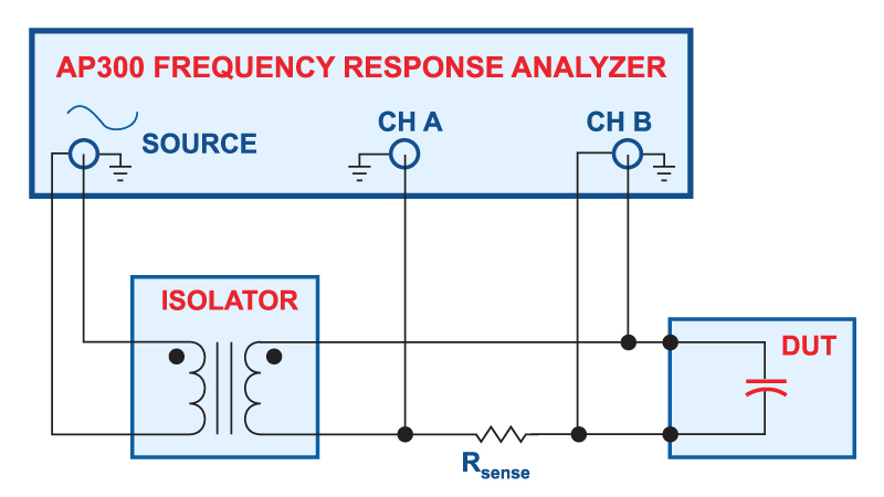
Figure 2: Measurement setup for low-impedance capacitors
Figure 2 shows how to make measurements of low-impedance capacitors with a frequency response analyzer [1]. Proper choice of sensing resistor, and proper RF layout of the test circuits will allow you to measure impedances as low as 1 mOhm with this test setup. While many component testers will only look at a single frequency, or a narrow range of frequencies, it is recommended that you sweep the frequency to see the impedance of the component under test from 10 Hz to at least 10 MHz.