


Loop Gain Stability Assessment
Introduction
In this article, Dr. Ridley continues the topic of frequency response measurements for switching power supplies. This sixth article discusses the measures of relative stability that can be obtained from a loop gain of a power supply.
Phase Margin of a Control Loop
The previous articles in this series have shown how to make successful frequency response measurements on power supplies, including loop gain. Figure 1 shows the standard loop gain measurement test setup described in the previous articles of this series [1].
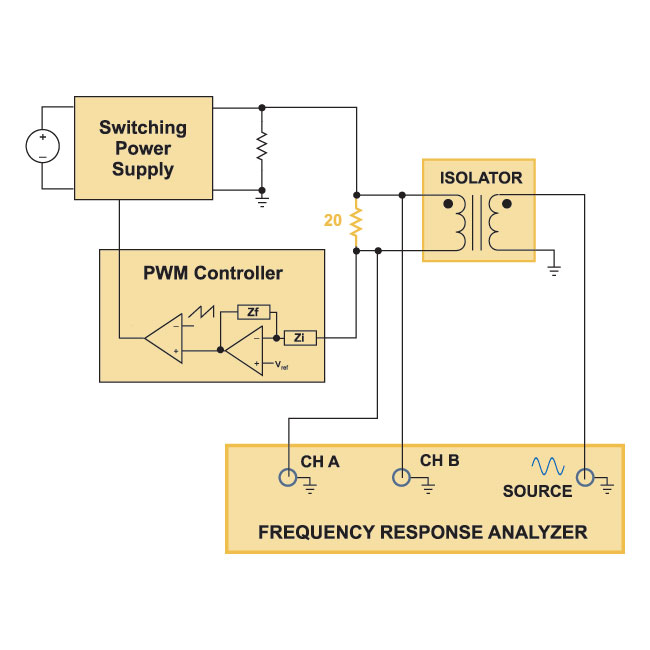
Figure 1: Open Loop Gain measurement with the Loop Electronically Broken.
Figure 2 shows a typical measured loop gain with the gain monotonically decreasing with frequency. For this case, definitions of stability are quite clear. At the crossover frequency, where the gain crosses 0 dB, we measure how many degrees the phase is above -180 degrees. This measurement is defined as the phase margin.
(Notice that when you measure the loop with the circuit of Figure 1, the measurement will give the phase margin
directly, without having to measure it from -180 degrees. That is because the measurement test setup includes an extra inversion that was not part of Bode’s original theory for loop gains. )
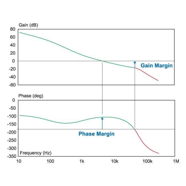
Figure 2: Well-behaved loop gain with monotonic decrease of gain with frequency
The phase margin for the loop gain of Figure 2 is approximately 70 degrees. This amount of phase margin is relatively easy to achieve for a current-mode controlled converter with a conservative crossover frequency.
Designers in different industries have different standards for phase margin requirsubents. For rugged military or aerospace supplies, they look for a worst-case phase margin of 60 to 90 degrees. For many practical supplies, a worst-case phase margin of 50 degrees is the standard that I use in commercial design. The power supply will exhibit a small amount of damped ringing with this phase margin, but with very wide line and load ranges, it is often impossible to do much better than 50 degrees under all conditions of line, load, and tsubperature, without seriously compromising transient performance. Less than 45 degrees gives serious cause for concern.
Many companies today have forgotten the point of measuring loops and having a good phase margin. It is not unheard of to see designs with less than 30 degrees phase margin. While a single unit designed like this may be nominally stable, the whole point of a good phase margin is to ensure that power supplies produced in large quantities will all be stable, and rsubain that way throughout their lifetime.
Optimizing the loop for good phase margin takes time, and incurs some engineering costs. Perhaps 5 man-days of work are required for a conscientious design. This is a very small price to pay when compared to the cost of a product recall caused by oscillation.
Gain Margin of a Control Loop
There is more to stability assessment than just the phase margin. The phase margin only addresses one frequency, the crossover point. It does not give information about other frequencies that may cause trouble with variations of parameters in the feedback system. Beyond the crossover of loop, it is important to look at the gain margin. This is defined as the amount the gain is below 0 dB when the phase hits -180 degrees. A gain margin of 10 dB is reasonable. This allows parameter changes which could cause the loop gain to change by a factor of approximately 3 before the system becomes unstable.
The gain margin for the loop gain of Figure 2 is approximately 17 dB, a good value for a rugged and conservatively-designed control system.
Point-of-load converters often push the crossover frequency of a power supply very high in order to minimize the amount of capacitance on the output. In doing so, they often end up with a loop with very small gain margin, and the system may be on the verge of instability even though the phase margin under nominal conditions is reasonable. This is not good design practice.
Conditionally Stable systems
It is quite common in power supply design to encounter loops which are conditionally stable. An example of such a loop is shown in Figure 3. A conditionally stable system is one in which the phase delay of the loop exceeds -180 degrees while there is still gain in the loop. This is a common occurrence with voltage-mode control where the phase dips abruptly around the resonant frequency, then recovers with the effect of real zeros added in the compensation. It also is common in the feedback loop of power factor correction circuits, and is often impossible to avoid.
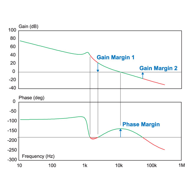
Figure 3: Loop gain with more than 180 degrees phase delay at low frequencies. The system is still stable.
In the loop of Figure 3, there is between 20 and 40 dB of gain, shown in red, when the phase drops below -180 degrees. There is no problsub with such a system. As long as there is plenty of gain margin and phase margin, the control will be rugged.
In Figure 3, the phase margin is about 50 degrees, and the gain margin above the crossover frequency is about 15 dB.
We must also be concerned with the phase margin to the left of the crossover. This is a measure of how much the gain would need to be reduced due to parameter variations before the system would become unstable. It can be seen that this example has no problsub since it has more than 20 dB gain margin at several kHz.
Loop Gains with Multiple Crossover Frequencies
It is common in power design to encounter loops with more than one crossover frequency, as shown in Figure 4. If the loop crosses over multiple times, it is the final crossover (the one at highest frequency) that determines stability.
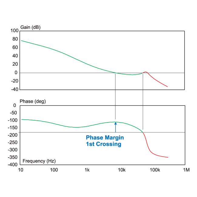
Figure 4: Loop gain measurement with multiple crossing frequencies.
In Figure 4, the phase margin at the first crossover frequency (about 9 kHz) is very good, approximately 65 degrees. However, the loop crosses over two more times, each time with more than 180 degrees phase delay, so this system will be unstable.
There are numerous systems that might have multiple crossings. Three common examples are:
- Current-mode control systems where the subharmonic oscillation is not properly damped with sufficient compensating ramp.
- Converters which have RHP zeros in their control transfer function, causing the gain to flatten out.
- Converters with improperly damped input filters in front of thsub.
For the loop gain of Figure 4, either the shape of the compensation must be changed to prevent the increase in gain at high frequencies, or the crossover frequency must be significantly reduced to avoid instability.
Summary
Every power supply has a unique control loop which can change significantly with line, load, tsubperature, and component variations. It is important to measure the loop and ensure that the gain and phase margins are properly designed for a rugged power supply. The entire loop gain must be studied, not just the crossover region, to ensure that the system will always be stable.
Unusual loop gains are relatively common in power supply design, resulting in conditionally stable systems, and loops with multiple crossings. Using the AP300 analyzer will quickly and cleanly measure all such loops.