


As with inductors, the design of a transformer is governed by a single design equation. Obey this, and the path to creation of new designs is clear
I have observed over the years that people fall into one of two categories when it comes to designing magnetics. First, you have those who know how to build something. They are usually seasoned engineers, or technicians, who know that there are simple and straightforward design methodologies to ensure success. Secondly, you have the rest of the engineering world who are deeply intimidated by the magnetics. There seem to be endless intractable equations, obscuring the elegant simplicity of ‘how to start a design’.
Theory is great for exercising the mind. However, there is no substitute for building magnetics and iterating the design. It is the only way to truly gain knowledge and experience. We have seen this applied to inductor design, and now we are going to turn our attention to the second magnetic element – the transformer.
Two Types of Magnetic Circuit Elements
There are just two types of magnetics available in circuit theory – a simple inductor, and an ideal transformer. If you have one winding on a core, you have an inductor. If you have two or more windings, or even just a tap on the single winding, you have a transformer. It won’t be an ideal transformer, that is only possible in a simulation, but we still call it a transformer.
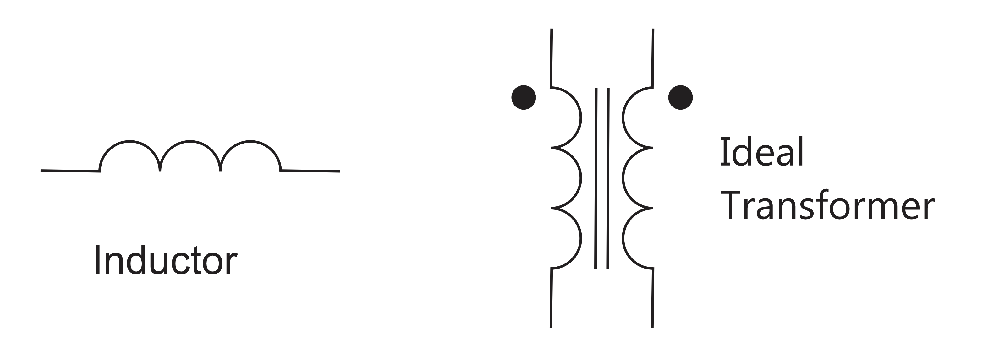
Figure 1: The Two Types of Magnetics Components
As we will see, when you try to build an ideal transformer, there are extra inductive components that must be added to fully explain its operation. That is what makes magnetics so interesting – proper control of these extra components differentiates the expert from the novice. Detailed construction techniques lead to very advanced designs without the need for endless equations.
But let’s start at the beginning. As we learned in previous articles, most publications on magnetics make the design process appear unnecessarily complex. For the inductor, we showed that there is just one equation that must be obeyed for proper design. Beyond this one equation, engineers are encouraged to use design iteration to explore the possibilities of a design task. For the inductor, the equation is:
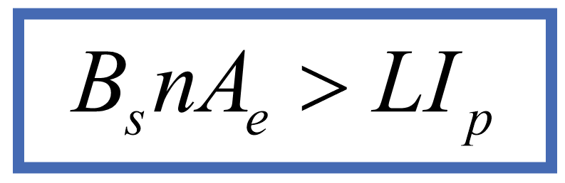
Figure 2: The Single Inductor Design Equation
This single equation tells us that for a given inductance and a peak current that it must carry, you need a certain minimum number of turns on a selected core in order not to saturate the core material. It is that simple. How you arrange those turns with wire, foil, litz or other materials will determine the performance of the inductor.
Transformers are more complex since they have two or more windings on them. However, they are a basic element in a circuit simulator, and their symbol on your schematic is also simple.
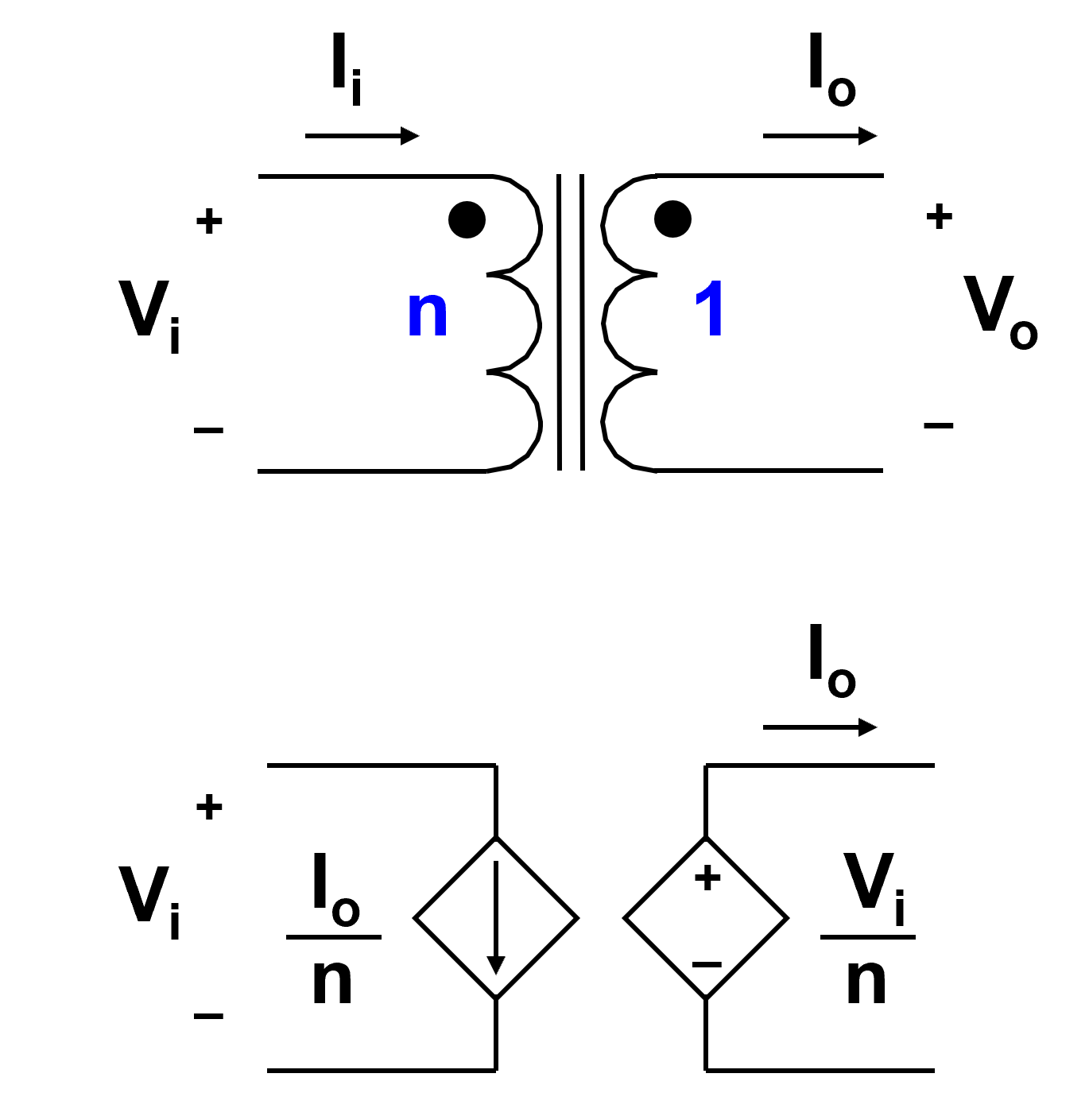
Figure 3: The Ideal Transformer and Its Equivalent Circuit
As you can see from the circuits in Figure 3, the operation of an ideal transformer is easily defined. If the transformer has an n:1 turns ratio, the output voltage of the transformer is just equal to the input voltage divided by n. Similarly, the input current to the transformer is equal to the output current divided by n. This simple equivalent circuit with two sources gives us some important insight. Notice that the power into the first winding is exactly equal to the power out of the second winding. In other words, there is no energy storage in an ideal transformer.
A consequence of this is that there is no inherent power rating for a transformer. We can push unlimited power into one winding and receive unlimited power out of the second winding. The lack of energy storage makes this possible. If you have worked with line-frequency transformers, you already know that. A transformer with a nominal rating of 50 W on its label is quite capable of giving you 500 W for a short time with no ill effects. When replacing linear supplies with switchers, it is easy to overlook this fact.
Building a Transformer
Figure 4 shows how a transformer is constructed. We have a core which is usually ungapped. Primary and secondary turns are usually wound one on top of the other, although there are exceptions to this. The core has a cross-sectional area for the given core size and shape, and a permeability determined by the material of the core.
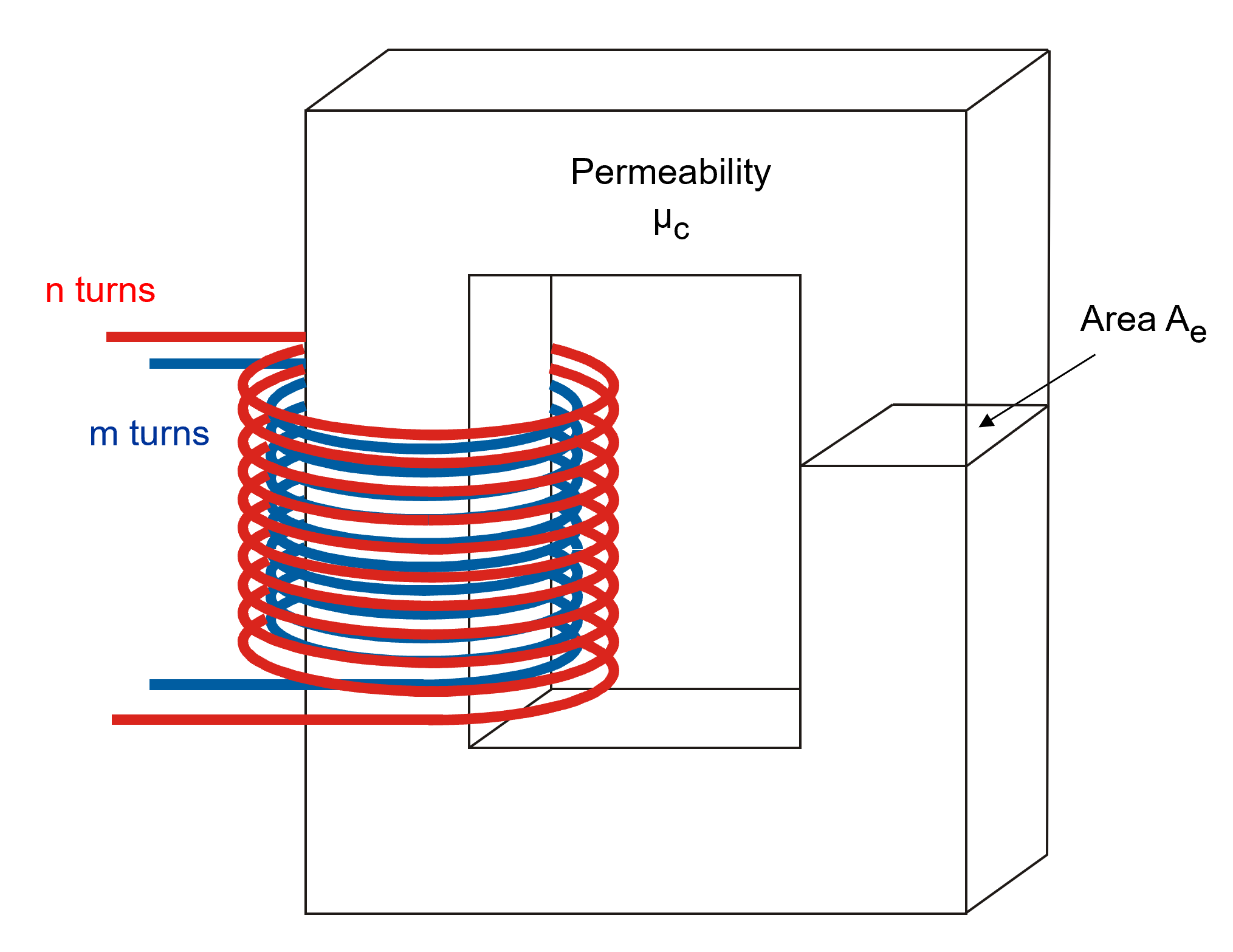
Figure 4: Construction of a Transformer
There are endless choices for the windings and their arrangement when making a transformer. Regardless of how the turns are arranged, or the core selected, it is impossible to make an ideal transformer. The ideal transformer can only exist in a theoretical circuit element. The core used to enclose the fields of a transformer adds many extra circuit elements to the device. The first, and most important of these is the magnetizing inductance, and it appears in the equivalent circuit as shown below.
Notice that we still have an ideal transformer in this circuit model, capable of processing unlimited power. However, in parallel with this ideal device is the magnetizing inductance of the transformer. This circuit element behaves like any other inductor – if we push too much current through it, we can saturate the material. This is usually a destructive event that must be avoided under all circumstances.
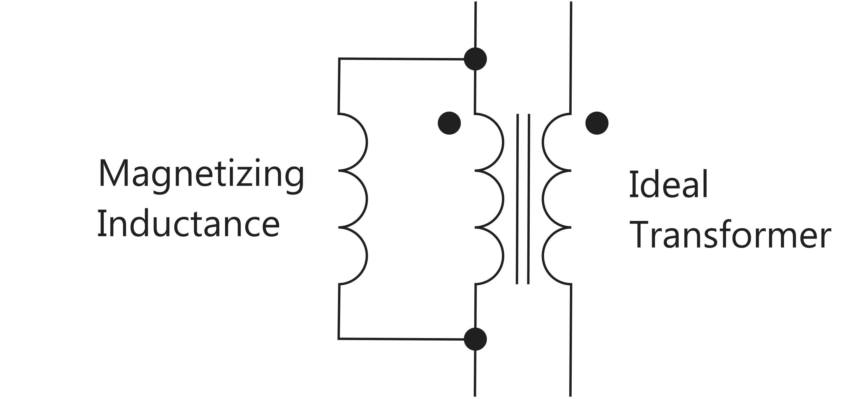
Figure 5: The Ideal Transformer with Parallel Magnetizing Inductance
The current that flows through the magnetizing inductance is NOT the load current. The magnetizing current is determined by the voltage waveshape applied to the transformer and has nothing to do with the current flowing in the ideal part of the transformer.
Figure 6 shows how we use the magnetic material in a transformer design. For a forward-type converter, the flux in the core starts at zero at the beginning of each cycle, and it is increased to the peak level of the material at the end of the on-time of the switch(es). For bridge converters, we can drive the core in two quadrants, and this can make the size of the core smaller. However, must be careful to keep the core flux centered around zero, which can be hard to control.
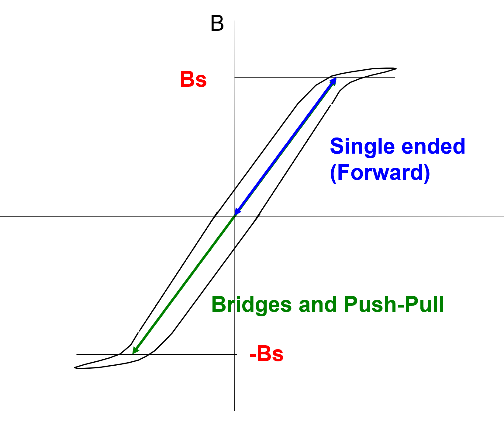
Figure 6: Flux Swing in a Transformer Core
One Equation for Transformers
Figure 7 shows the applied voltage waveform on a transformer, and the corresponding magnetizing current. The current ramps up during the on-time of the switch, and ramps down again to zero during the reset period. Reset is achieved through various schemes. Each of them involves applying a negative voltage across the primary of the transformer to reduce the magnetizing current.
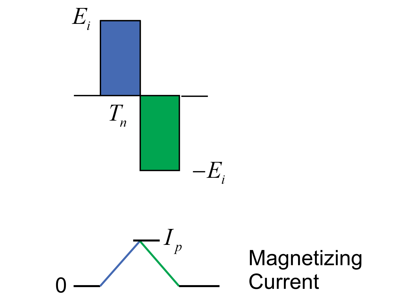
Figure 7: The Effect of Applied Voltage and the Magnetizing Current
The slope of the magnetizing current during the on-time of the switch, shown in blue, is determined by the value of the inductance, and the voltage applied to the transformer. It is easy to show that there is an equivalence for this magnetizing inductance and current as follows:
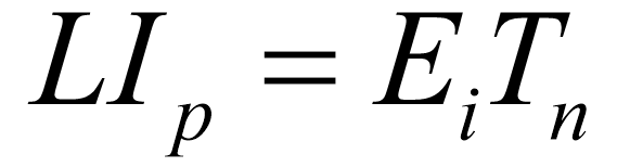
Figure 8: Equation Governing the Charging and Peak Current in the Magnetizing Inductance
Notice that the left-hand side of this equation is part of the single equation we use to design inductors. We could use the same equation for transformer design, but we don’t know the value of the inductance with any degree of certainty. That doesn’t stop us from moving forward and substituting the right-hand side of the equation to get the design equation for a transformer.

Figure 9: The Single Design Equation for Transformers.
Having ONE EQUATION that is the KEY equation for transformers is an enabling revelation. You don’t need to go any deeper to start winding transformers. For a transformer operating in a converter, we know the maximum voltage and the maximum on-time of the switch. If we take a maximum flux level of 0.3 T for a ferrite material, then any given core with its area has a defined number of turns needed to avoid saturation. A flux level of 0.3 T that is used for design in reliable commercial power supplies. High-reliability supplies may reduce this level to perhaps 0.25 T or 0.2 T, depending on the application.
We could theoretically double the value to 0.6 T for bridge converters, recognizing that the flux can swing in both directions. However, we need to concern ourselves with the initial start-up of the transformer. Flux can be at zero. Large transient events in a converter can range from very light load to full load. It is a cautious judgement call, backed by ample testing, that determines how much of the available headroom is to be used.
Other Design Equations and Considerations
Having ONE EQUATION simplifies things. However, when you read magnetics text books or application notes, you will find many additional design equations and constraints. As with inductor design, most of these are an added attempt to eliminate design iteration and solve for the “optimum” design in one attempt. In my opinion, this is not useful. You cannot possibly optimize every design with the same set of constraints and guidelines for every design. Temperature, cooling arrangements, and structures vary widely from one application to another.
In that regard, we ignore the conventional guidelines of fill factor, window-area product, and conductor current density. The assumptions found in text books simply do not apply to modern magnetics structures. They are derived from the old days of line-frequency magnetics. It is much better to use the ONE EQUATION and learn as you go.
Leakage Inductance - An Important Constraint
While there is just one equation to avoid saturation, we have to consider other constraints. Before you go headlong into winding transformers,we need to learn about leakage inductance of a transformer which will most definitely steer the direction of the design. We will talk more about that in the next article of this series. We will see that the choice of turns counts is often up against hard limits due to leakage, and this removes design freedom, but gives the advantage of providing a clear direction to the design.
Summary
One design equation is needed for creating transformer designs. This equation can be found in all magnetics books but is not highlighted as the ONE EQUATION that is essential. It is buried under hundreds of other equations. Once this is understood, it is very straightforward to begin designing and building your own transformers.
Transformers are intriguing elements in that they do not store energy and hence do not have an explicit power rating. This leads to a very wide variety of sizes and shapes that you will see in production designs. One company’s 100 W transformer core will be used at 800 W by another company. While this is at first puzzling to see, understanding the ONE EQUATION gives design insight and lets you get started on the iteration process of development.
There is no substitute for practical experience in transformer design. In our hands-on workshop, attendees successfully design and build their first transformer in our initial lab session. Many attendees then iterate the design in the same session, optimizing the transformer performance with the second attempt. There is no substitute for practical experience in this process - all the theory in the world cannot teach you the practicalities of working with different wires, bobbins, foils, and cores.
References
- Magnetics Design Videos and Articles in our Power Supply Design Center.
- RidleyWorks™ design software contains complete magnetics design and advanced analysis. A free Buck Designer is available to download.
- Learn about proximity losses and magnetics design in our Hands-On Workshops for power supply design. This is the only hands-on magnetics seminar in the world.
- Join 3000 design engineers at our new Facebook Group. Advanced in-depth discussion group for all topics related to power supply design.