


[049] Forward Converter Design - Part XV Cross-Regulation

Cross-regulation characteristics of the five-output forward converter.
Introduction
This article continues the series in which Dr. Ridley documents the processes involved in taking a power supply from the initial design to the full-power prototype. Initial testing on a new five-output design shows the cross-regulation achieved.
Five-Output Coupled-Inductor Design
With the second turn of the printed circuit board, the specifications were modified as follows:
1. Output 1 – 32.5 VDC @ 7A isolated
2. Output 2 – 32.5 VDC @ 7 A isolated
3. Output 3 – 32.5 VDC @ 7A isolated
4. Output 4 – 32.5 VDC @ 7 A isolated
5. Output 12 – 12 VDC Bias power and regulated output, primary referenced
6. Maximum power 350 W (only one output fully loaded at a time, application is for audio.)
7. Input – 180 – 265 VAC
8. Power Topology: Two-switch forward
Notice that the voltage levels are adjusted somewhat from the original design with three outputs. As a power supply designer, it is always a good idea to be flexible to system changes that come from the power supply users. This almost always happens during a product development cycle.
Figure 1 shows the schematic of the five-output forward converter. A single core inductor, L1, is used with five windings, one for each of the outputs. This coupled-inductor approach provides the best cross-regulation between each of the outputs. There are two major advantages of coupled inductors – firstly, all of the outputs are tied together through the transformer action of the inductor, preventing them from having individual resonant frequencies. Secondly, regardless of individual loading on each of the outputs, the coupled inductor forces all of the outputs to be in either continuous or discontinuous mode concurrently, greatly improving the regulation.
As shown in an earlier part of this series, excellent regulation was achieved with a wide variation of output loading for three outputs. With the new design, it is important to establish the cross-regulation with the two extra outputs.
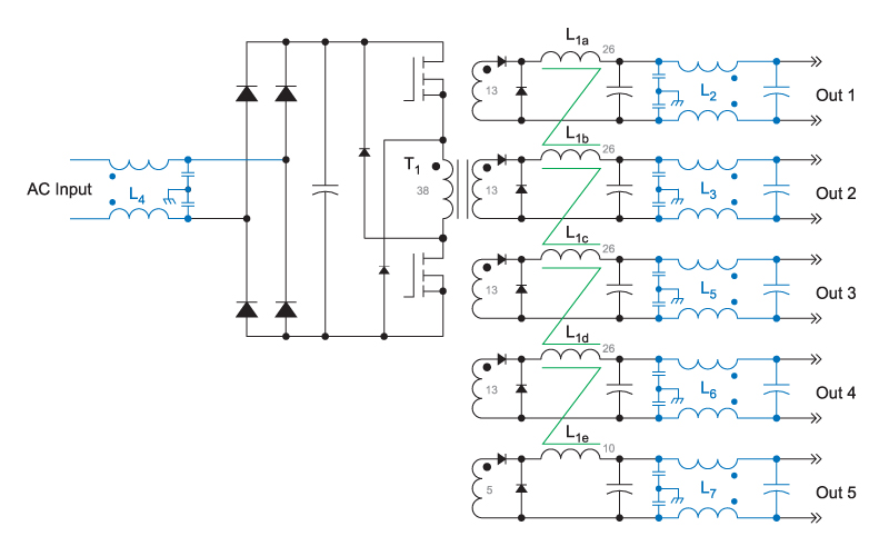
Figure 1: Forward Converter with Five Coupled-Inductor Outputs
Notice that Figure 1 shows common-mode filters on all of the power outputs. These filters are essential for proper testing of the converter, as discussed later.