


Further examples of why step-load testing will not give you the design information that you need.
Introduction
In this article, Dr. Ridley continues the topic of frequency response measurements for switching power supplies. This eighth and final article in the series shows how step-load testing cannot provide sufficient insight into how to redesign systems that are near instability.
Step Load Testing
The seventh article of this series showed three different converter step-load responses. For the first response, it was shown how a simple gain reduction stabilized the system. However, the other two responses do not improve with a reduction in gain, as we will see, and the step-load test offers no guidance on how to improve the design.
Buck Converter Transient Response – Too Little Gain
Figure 1a shows a step-load transient response for a buck converter with voltage-mode control. The converter has a 4 kHz oscillatory response, indicating insufficient phase margin.
In the previous article, reduction of loop gain was the proper solution to improve the response. However, in the buck converter case shown here, reducing the gain makes the stability problem worse. The step load response is even more undamped, as shown in Figure 1b
The proper solution in this case is to increase the gain of the feedback loop, resulting in the response of Figure 1c.
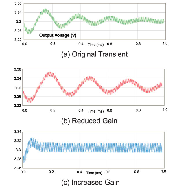
Figure 1: Transient Load Response of Buck Converter (a) Before (b) After Gain Reduction and (c) After Gain Increase.
Looking at the loop gains of Figure 2 gives us insight into what is happening. The green curve shows the original gain, the red curve shows the decreased gain, and the blue curve shows increased gain. The phase margins at the crossover frequencies give us the characteristic transient response. For the red curve, we can see that the loop crossover has dropped close to the LC filter resonant frequency, resulting in only 10 degrees phase margin.
For the blue curve, the crossover is moved to a much higher frequency, away from the LC filter resonance, where the phase delay is much less. This results in a stable system with 60 degrees phase margin. Further changes can be made to stop the phase dropping down close to -180 degrees, and the loop gain information provides clear information on how to proceed with this.
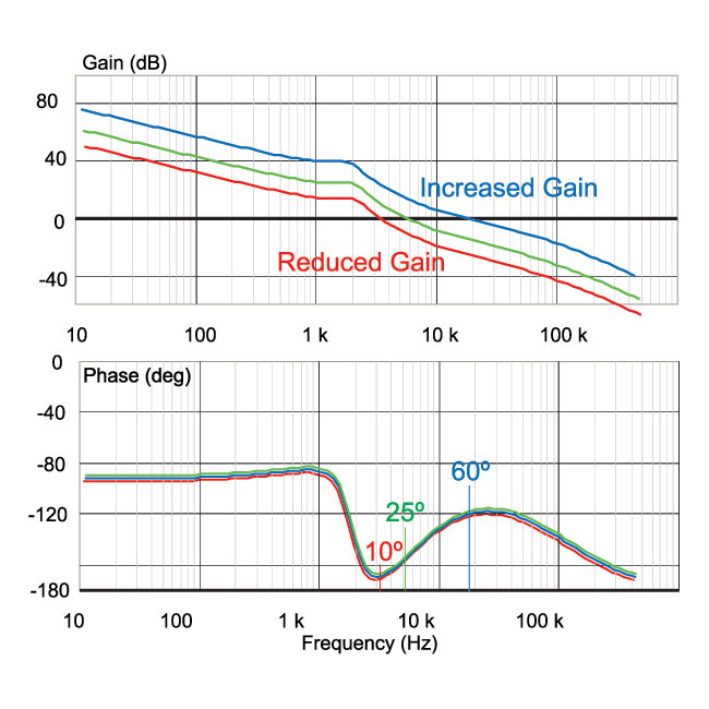
Figure 2: Loop Gain and Phase of the Buck Converter.
The example given in the last article had a loop gain which crossed over in a region where the phase margin was decreasing with frequency. For the buck converter with voltage-mode control, it is common for the opposite to be true. Just above the filter resonance, the phase improves as the frequency increases. This information is only available from the loop gain, and cannot be seen from the step-load response.
Flyback Transient Response – Incorrect Compensation
Figure 3a shows the transient response of a flyback converter, with a 5 kHz oscillation. A reduction in gain of the loop results in the waveform of Figure 3b, and the system is still only just stable. The result of an increase in gain is shown in Figure 3c, and the system remains undamped. For this system, the ringing cannot be eliminated by changing the gain alone, and more complex adjustments must be made.
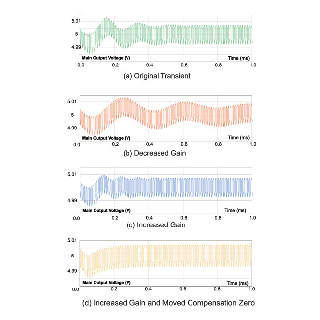
Figure 3: Transient Load Response of Flyback Converter (a) Before (b) After Gain Reduction (c) After Gain Increase (d) After Compensation Shaping.
The loop gains of Figure 4 give much more insight. The green curve shows the original gain, the red curve shows the decreased gain, and the blue curve shows the increased gain. The phase margins at the different crossover frequencies are 15, 35, and 40 degrees respectively. This is not enough to guarantee stability for a product, and additional changes must be made to improve the phase margin.
The gold curve shows the loop gain with the first compensation zero moved to a lower frequency. With this change, the phase margin is increased to 60 degrees, and the design is optimized.
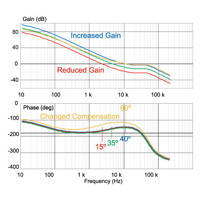
Figure 4: Loop Gain and Phase of the Flyback Converter.
Trying to arrive at this new compensation with only step-load testing would be extremely difficult. There are so many degrees of freedom in changing the compensator, it is unlikely that an optimal design would be reached. Only by looking at the loop gain can we see which design approach is correct.
Summary
This article shows how step-load testing is not useful for correcting systems that have insufficient stability margin. In general, power supplies have very complex control loops, especially when the effects of additional filters, multiple outputs, and different modes of operation are considered. Relying on the very limited data available from a step-load test (or output impedance measurements) to guarantee stability over the lifetime of a product is not recommended.
The last eight articles in this series have addressed the issue of frequency response measurement, a powerful tool for development of power supplies and power electronics systems. There are many more topics in this area, and I will return to some of the more complex issues in future articles.
References
- Join our LinkedIn group titled “Power Supply Design Center”. Noncommercial site with over 7000 helpful members with lots of theoretical and practical experience.
- For power supply hands-on training, please sign up for our workshops.
- “Frequency Response of Switching Power Supplies, Parts 1-7”, Power Systems Design Magazine, Design Tips Archive. http://www.powersystemsdesign.com
- “AP Instruments AP300 User Manual”, http://www.apinstruments.com/files/Model300.pdf