


[056] Manual Frequency Response Measurements for Magnetics - Part II
How to improve manual impedance measurements with a good signal source.
Introduction
In this article, Dr. Ridley provides further insight into frequency response measurements of transformers and inductors using equipment that you probably already have in your laboratory. An improved signal generator allows errors in short-circuit measurements to be greatly reduced.
The Importance of Impedance Measurements
As mentioned in the last article in this series, impedance measurements of transformers and inductors are an essential step in producing quality magnetics for prototyping and production. Ideally, the measurements of magnetics impedance should be made with a properly calibrated and automated piece of test equipment [1]. However, many students of power electronics and engineers beginning their careers only have access to the most basic laboratory instruments. The impedances of all magnetics should still be measured with the techniques described in these articles. The time spent on this process is very valuable.
Manual Setup of Impedance Measurements
Figure 1 shows the recommended test setup for manually measuring magnetic components. The device under test is connected in series with a 1-ohm test resistor, and a signal applied across the series combination. The voltage across the 1-ohm resistor, representing the current, is measured with one channel of an oscilloscope. The voltage across the series combination is measured with the second channel.
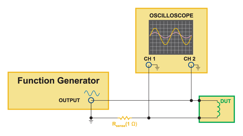
Fig. 1: Schematic of How to Measure Frequency Response of Magnetics Using a Signal Generator and Oscilloscope.
Figure 2 shows a photograph of the actual lab test setup. A small test fixture containing the sense resistor was used to improve RF layout issues of the test setup [1]. It is very important that the impedance of the sense resistor setup be accurate up to the highest measurement frequency.
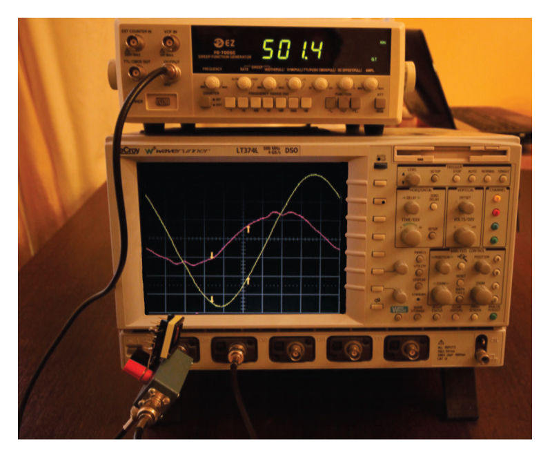
Fig. 2: Photograph of Manual Magnetics Impedance Test Setup.
This setup was used in the last article in this series. Very good results were obtained for the open-circuit measurements of a transformer. The measurements with the manual setup and with the AP300 analyzer setup were in very close agreement.
Experimental Results for Short-Circuit Impedance Measurements
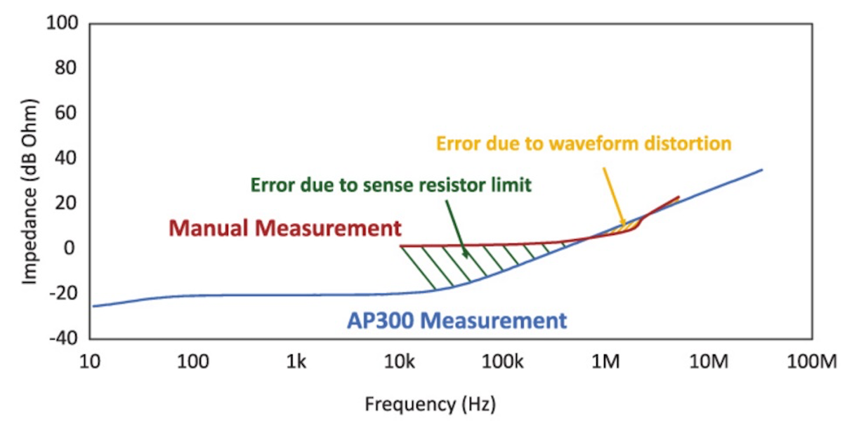
Figure 3 shows the results of measurements with the transformer secondary shorted. In this case, the manual measurements did not agree very well with the AP300 measurements.
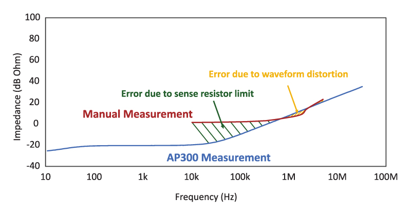
Fig. 3: Comparison of Manual Transformer Short-Circuit Impedance Measurements and Automated Measurements with the AP300.