


[057] Output Impedance Measurements and Loop Gains
The relationship between loop gain and output impedance
Introduction
In this series of articles, Dr. Ridley discusses the four important frequency-response measurements to be made during full characterization of a switching power supply. The important relationships between loop gain and output impedance measurements are highlighted in this first article. If you want to ensure a rugged and reliable design, both of these parameters must be directly measured.
Power Supply Transfer Function Measurements
There are four fundamental transfer functions that characterize the small-signal performance of a switching power supply. They are as follows:
1. Loop gain and phase – determines the stability of your design, and available margin to accommodate variations in components.
2. Output impedance – determines the output regulation, dynamic load response, and susceptibility to complex loading.
3. Audiosusceptibility – determines the transmission of noise from input to output.
4. Input impedance – determines the sensitivity of the power system to input filter or input power system components.
These parameters are listed in the order in which they are commonly measured and used in the industry.
A direct loop gain measurement is essential to guarantee stability of a power supply design over the lifetime of its usage in the field. Most reliable power supply designs include loop gain measurements as part of the design verification process.
If loop gain is the only parameter that is measured, there can be a tendency to focus too much on the stability at the expense of better closed-loop performance. More experienced designers include an output impedance measurement as part of their design verification and documentation, even if it is not directly required by the end customer. The output impedance measurement contains a wealth of information about how the converter will respond to dynamic load changes at different frequencies. It also provides information about the susceptibility of the power supply to complex loads. This allows a designer to predict with confidence how a converter will work when presented with different load scenarios.
An audiosusceptibility measurement gives information on the transmission of noise from the input of the power supply through to the output. It is usually a requirement of the documentation package in the aerospace industry. This measurement is more difficult to make since a perturbation must be injected on top of the high-power input rail. Most commercial designs omit this measurement.
A measurement of input impedance is also usually required by the aerospace industry. It is very useful for anyone designing large and complex power systems. As with audiosusceptibility, this is a more difficult measurement to make, but once injection is set up for the audiosusceptibility measurement, it is easy to measure the input impedance. (Note: most systems designers that perform an input impedance measurement do not apply the results properly, and this is an advanced topic discussed in a later article in this series.)
Output Impedance Measurements
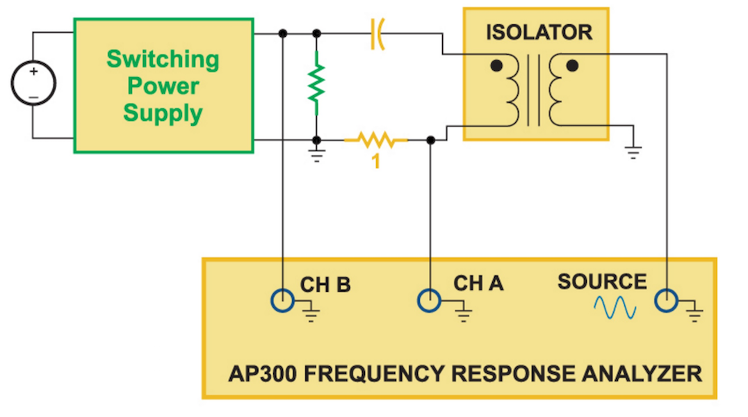
While loop gain measurements are essential for showing the stability of a power supply, it is the output impedance that directly shows how well a converter will regulate and how it will respond to changing loads. In order to measure output impedance, current must be injected into the output of the power supply as shown in Figure 1.

Fig. 1: Output impedance is measured by driving a current into the output terminals of a power supply