


[058] Audiosusceptibility Measurements and Loop Gains
The relationship between loop gain and audiosusceptibility PSRR
Introduction
In this series of articles, Dr. Ridley discusses the four important frequency-response measurements to be made during full characterization of a switching power supply. The important relationships between loop gain and audiosusceptibility measurements are highlighted in this third article. As with output-impedance measurements, it is possible to extract a calculated loop gain from the audiosusceptibility measurements, but direct loop gain is recommended to guarantee rugged stability.
Power Supply Transfer Function Measurements
There are four fundamental transfer functions that characterize the small-signal performance of a switching power supply. They are as follows:
- Loop gain and phase – determines the stability of your design, and available margin to accommodate variations in components.
- Output impedance – determines the output regulation, dynamic load response, and susceptibility to complex loading.
- Audiosusceptibility – determines the transmission of noise from input to output.
- Input impedance – determines the sensitivity of the power system to input filter or input power system components.
The first two parameters, loop gain and output impedance, were discussed in the first article of this series. It is highly recommended that both of these measurements are made on every switching power supply that you design and build. The loop measurement is essential to guarantee stability over the lifetime of the power supply, and the output impedance gives comprehensive information about the performance in the presence of load variations.
An audiosusceptibility measurement gives information about the transmission of noise from the input of the power supply through to the output. It is usually a requirement of the documentation package in the aerospace industry. This measurement is more difficult to make than output impedance since a perturbation must be injected on top of the high-power input rail. Most commercial designs omit this measurement, although it can be very useful for getting maximum performance out of your power supply. With the injection techniques recommended in this article, it is not that hard to make the measurement and it is usually well worth the time.
Audiosusceptibility Measurements
Audiosusceptibility directly shows how well a converter rejects noise appearing on the input. In order to measure audiosusceptibility, a voltage source must be injected in series with the input of the power supply as shown in Figure 1.
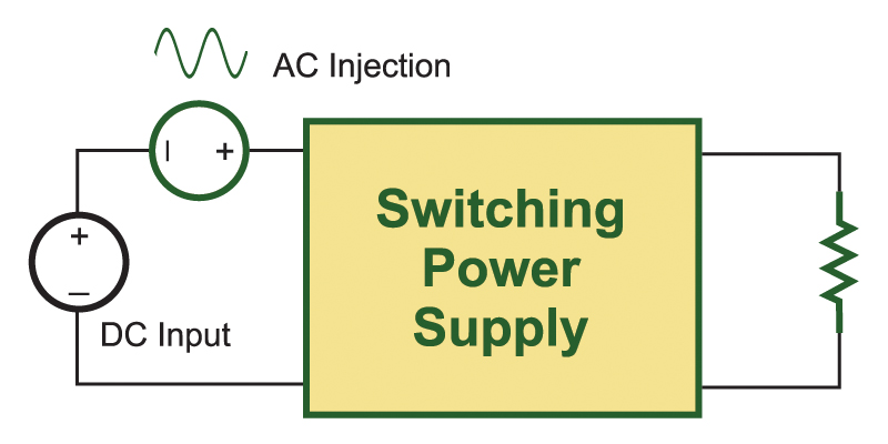
Fig. 1: Audiosusceptibility is measured by adding a voltage signal at the input terminals of a power supply.
Figure 2 shows how this is implemented practically using a frequency response analyzer and a few discrete device. The output of the analyzer is connected to wide-bandwidth isolator which is then AC coupled to a FET hooked up as a voltage follower. The size and rating of the FET may vary according to the power level and voltage level of the converter that is being driven. This injection technique is much simpler and more cost effective than inserting a high-power amplifier in series with the input source, and will allow sufficient signal to be injected for most applications.
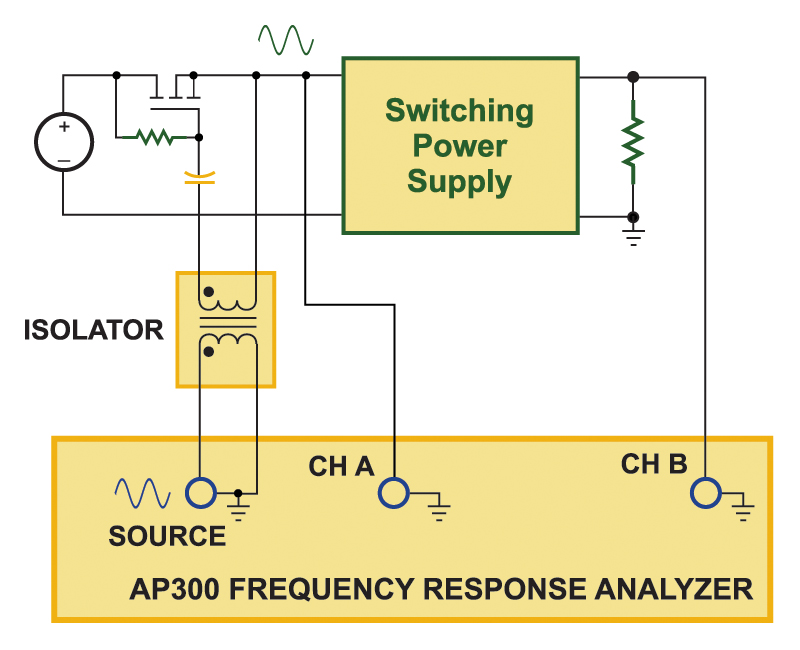
Fig. 2: Practical test setup for injecting voltage signal and measuring audiosusceptibility.
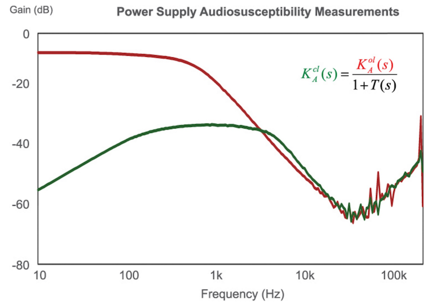
It is useful to plot both the open-loop and closed-loop audiosusceptibility to show how well your control design is implemented. These two measurements are shown in Figure 3 for a sample flyback converter operating with voltage-mode control.