


For most power supply applications, a handful of topologies continue to be used after more than 30 years. Simplicity and ruggedness keep these circuits relevant today.
Introduction
At the beginning of modern power supply design, about thirty years ago, there were a handful of topologies that served the industry well. In the 1980s, an explosion of research into new and advanced power conversion techniques created hundreds of new topologies that could be used. Today, mainstream industry has reverted back to the early topologies. The same handful of circuits provides the best solutions for most applications.
The Nine Most Useful Power Topologies
In the beginning of power supply design, there were three fundamental converters: the buck, boost, and buck-boost. Early analysis papers cover just these topologies. There were also converters that behaved exactly the same as these fundamental topologies. They were considered to be in the buck, boost, and buck-boost families, with isolation being included in the circuit. Included in the buck converter family are the forward, two-switch forward, half-bridge, full-bridge and push-pull. The boost has an isolated version that can be built with a bridge or push-pull circuit. The isolated buck-boost circuit is the well-known flyback converter.
It is an intriguing research exercise to invent new power topologies and study their operation. This formed a large part of research in the past, especially during the 1980s. Some fascinating circuits were invented that stretch the mind to fully understand their operation. A paper from Caltech came up with over 300 new topologies which used an additional switch and diode. For a while it seemed as if the old standby topologies were in jeopardy of being replaced.
It was a very confusing time for many designers who needed to produce products. After reading conference papers, engineers were tempted to try exotic new topologies that promised superior performance but which proved to be very difficult to implement in production.
As a result, the industry came full circle. Now it relies on the original basic topologies for nearly all designs. Exceptions are made for some very high density applications, or for unusual voltage and power ranges, but the working engineer can almost always get the job done with the basic set of circuits.
That is not to say that industry has not made progress. It has come a long way—just not through the usage of fundamentally different circuit topologies. The main advances have been in judicious use of the correct circuit for the right application, partitioning of power into smaller pieces (such as the motherboard VRMs and point of load converters), advanced packaging, new silicon devices, and careful application of low-loss switching for some of the topologies.
1. Buck Converter
The buck converter is the most fundamental of all power supplies. It supplies a lower voltage output than the input, and is used at all power levels where isolation is not required.
As shown in Figure 1(b), the diode of the buck converter can be replaced with an active switch when the output voltage is low. This provides efficiency advantages. Caution is required when using discrete parts since avoiding overlap of the two switches is essential.
Probably more buck converters are built than any other converter. They form the basis for microprocessor power supplies, providing over 100 A to the load. Modern design techniques break the total load into smaller pieces, using several parallel buck converters. This results in a final power system which can switch faster. It is also smaller and more efficient.
When working with these converters, don’t forget that the input is noisy. Good power designers will have input filters on the front end of their buck converters, preventing the large switching currents from creating noise issues elsewhere on the board.
The buck converter becomes less optimal as the input-to-output voltage ratio increases. A 10:1 step down is reasonable as an extreme. Beyond this, the silicon is stressed hard and a transformer topology may be more appropriate.
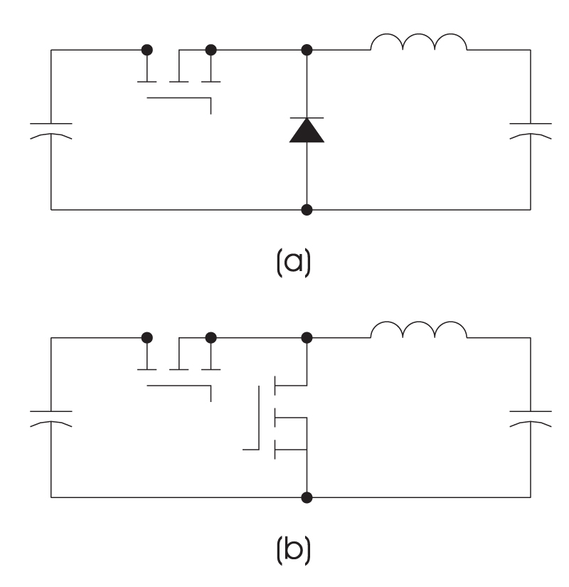
Figure 1: Buck Converter
Applications: Step down without isolation for power levels from less than 1 W to over 1 MW.
Strengths: Low noise output.
Cautions: Noisy input requires filtering. Don’t try to step down too much.
Advanced application: Synchronous rectifiers, multiphase for current sharing.
2. Forward Converter
If your system requires isolation or a large step down ratio, it can be provided by the forward converter. This inserts a transformer in the circuit and allows appropriate scaling of the input voltage. The transformer also inserts complications – the voltage stress on the switch is increased, and the core must be properly reset when the converter is turned off. In general, forward converters only operate to a 50% duty cycle. The rest of the period is reserved for transformer reset.
More advanced versions of the forward converter can be used in resonant mode, or with synchronous rectifiers for low voltage outputs.
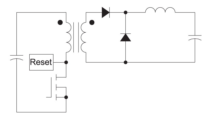
Figure 2: One-Switch Forward Converter
Applications: Isolated outputs for power levels from less than 1 W to about 100 W
Strengths: Low noise output, single ground-referenced switch.
Cautions: High voltage on the switch. Noisy input requires filtering. Transformer reset circuit needed. Maximum of 50% duty cycle.
Advanced application: Synchronous rectifiers, resonant converters, multiphase for current sharing, resonant reset of the transformer.
3. Two-Switch Forward Converter
The power level of the single-switch forward converter is limited by the voltage stress on the switch. At higher power levels, the converter of choice is the two-switch forward converter, shown in Figure 3. This is the most rugged of all the isolated converters, providing a voltage clamp on the primary power switches. It is used in applications up to 1 kW or higher.
Both switches are turned on simultaneously, and the top switch requires an isolated gate drive. The transformer core is automatically reset through the same diodes that clamp the voltages of the switches to the input voltage source.
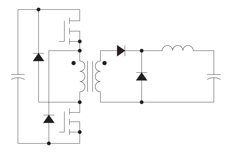
Figure 3: Two-Switch Forward Converter
Typical Applications: Isolated outputs for power levels from less than 50W to over 1000 W
Strengths: Low noise output, clamped primary switch voltages. Very rugged circuit.
Cautions: Noisy input requires filtering. Maximum of 50% duty cycle.
Advanced application: Synchronous rectifiers, multiphase for current sharing.
4. Half-Bridge Converter
The half-bridge converter has the apparent advantage over the two-switch forward of driving the core with a symmetrical waveform as each switch is alternately turned on. For years, engineers debated the relative merits of the half-bridge and forward. Once current-mode control became standard, the half-bridge converter fell out of favor as it does not work well with current mode control.
Only recently has it begun to re-emerge. Some examples include ballast supplies that need an ac output, and high-density power supplies that switch at very high frequencies, where the reduced core loss of the half-bridge becomes the deciding factor. The topology works well for the non-regulating bus converters of recent years.
For off-line applications, the current-mode issue and other complications of the half-bridge still make the two-switch forward the preferred approach.
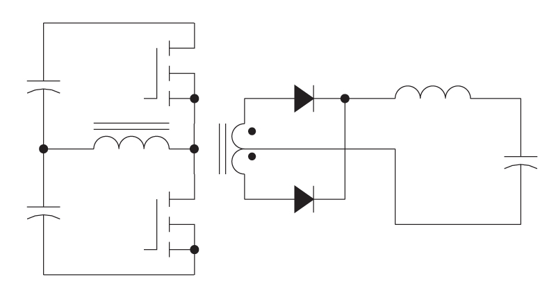
Figure 4: Half-Bridge Converter
Applications: Isolated outputs for power levels from less than 50 W to 500 W
Strengths: Low noise output, clamped primary switch voltages.
Cautions: Gate drive noise problems leading to cross-conduction, transformer flux balancing, input capacitor balancing, current-mode control problem. Not recommended for most cases
Advanced application: high-frequency bus converters with regulated input, synchronous rectifiers.
5. Full-Bridge Converter
As power levels exceed 500 W or so, some designers will take a pair of two-switch converters in parallel to supply the load. The primaries are switched out of phase with each other to minimize input noise. This is certainly a rugged and reliable approach for high power applications, and it minimizes development time.
Another approach is to replace the diodes in the primary of the two-switch forward with two more switches, and alternate the switching of the diagonal legs to provide the full bridge converter shown in Figure 6. The full bridge provides a lower parts-count solution than a pair of forwards, and is certainly the right choice if you have extra time for development.
Advanced designers use the full bridge in the phase-shifted mode, where the primary switches are always on 50% of the time. This minimizes switching losses in the primary, and eliminates the need for a primary snubber since the leakage inductance energy is circulated in the primary.
However, great care must be taken with this circuit not to ever overlap the drives on the side legs of the bridge. With the high-side drives required, this can be problematic, and solved with gate-drive transformers and careful layout.
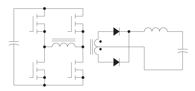
Figure 5: Full-Bridge Converter
Applications: Isolated outputs for power levels from 200 W to over 5000 W
Strengths: Low noise output, clamped primary switch voltages.
Cautions: Gate drive noise problems leading to cross-conduction, transformer flux balancing.
Advanced application: Phase-shifted operation, current-doubler operation, synchronous rectifiers. High-frequency bus converters with regulated input.
6. Push-Pull Converter
The last of the buck-derived converters is the push-pull. The push-pull converter has two ground-referenced switches, making it easy to drive directly from a PWM control chip. However, its application is limited to low-voltage inputs since each switch sees double the input voltage, plus any leakage energy spikes. It is a common circuit for battery input to higher voltage outputs, but it is not recommended for off-line applications.
It has also been applied successfully in high-frequency bus converters where the input voltage is tightly regulated, such as the half and full-bridges converters.
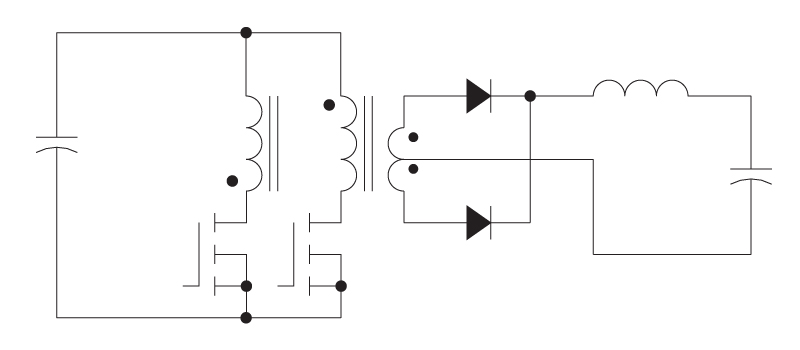
Figure 6: Push-Pull Converter
Applications: Low voltage input, isolated outputs for power levels from less than 1 W to about 500 W
Strengths: Low noise output, ground-referenced power switches.
Cautions: Transformer flux balancing, high voltage on input devices.
Advanced application: high-frequency bus converters with regulated input, synchronous rectifiers.
7. Boost Converter
The boost converter is the opposite of the buck – it only steps voltage up, its input is quiet, and its output is noisy. It is an ideal choice if you need step up without isolation, and it also finds very wide usage in power factor correction circuits which generate a high-voltage dc bus from the input ac line.
The boost converter is usually seen only in its nonisolated version. Which bridge and push-pull boost circuits can be built, they have issues with start-up that require extra power windings to get the circuit up to full output voltage without overcurrent in the power switch.
Figure 7: Boost Converter
Applications: Non-isolated step up, power from 1W to greater than 1 kW, power factor correction.
Strengths: Low noise input, clamped output voltage.
Cautions: Use current mode control to provide good response with this RHP zero converter.
8. Buck-Boost Converter
The buck- boost converter combines the step down of the buck, together with the step up of the boost. Shown in its simplest form in Figure 8, it provides a nonisolated and inverted input. Since this is not a particularly common requirement, and since it has a high-side switch, it is not a particularly common circuit in industry.
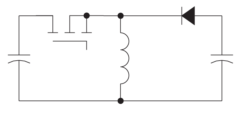
Figure 8: Buck-Boost Converter
Applications: Non-isolated step up or step down, inverted output, power from 1W to greater than 100W.
Strengths: Multiple outputs are easy to add.
Cautions: Current mode control for RHP zero, noisy input and output.
9. Flyback Converter
The flyback circuit is the isolated version of the buck-boost converter. After the buck converter, it is the most common circuit made. It is popular due to its low parts count, single magnetic element for both energy storage and transformer action, and for the ease it provides in generating multiple outputs.
The flyback converter has many modes of operation – discontinuous mode, continuous mode, quasi-resonant, etc. They are all in common usage. The drawbacks are the high voltage on the power switch, which usually must be clamped, the high noise output which benefits from a second filter, and a power limit corresponding to about 10 A output current.
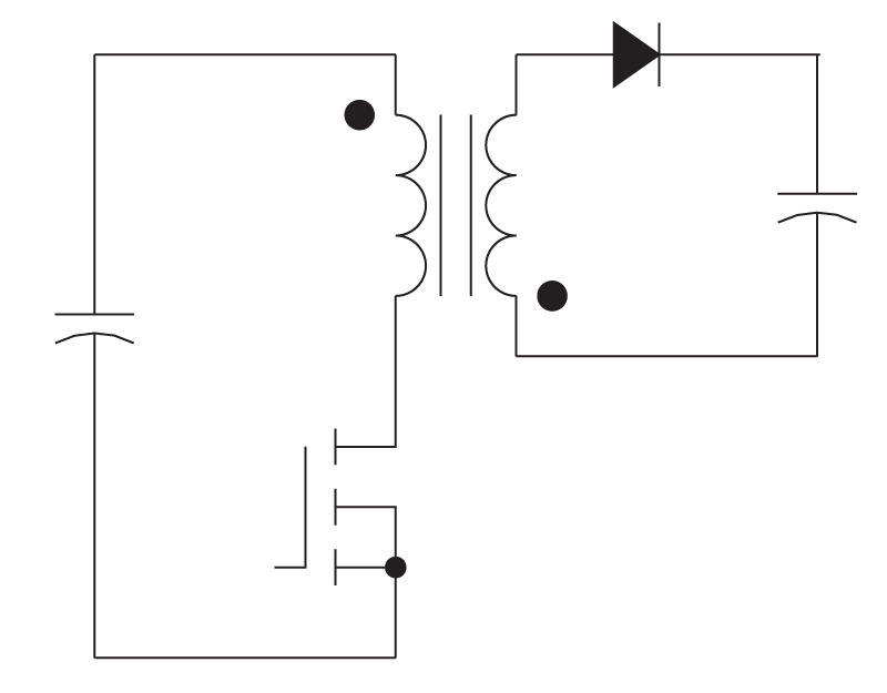
Figure 9: Flyback Converter
Applications: Non-isolated step up or step down, inverted output, power from 1W to 100W.
Strengths: Single ground-referenced switch, automatic core reset, multiple outputs are easy to add.
Cautions: Current mode control for RHP zero, noisy input and output. Limited to about 10 A output current
Advanced application: Quasi-resonant operation, synchronous rectifiers.
Cascaded Converters
Most power system designs are done with the above topologies. Sometimes, though, you run into a situation that calls for more functionality than can easily be provided with a single standard power stage. Rather than trying to research other topologies, one of the best approaches is to use a cascade of topologies where each serves its own function.
For example, if you need a very high step up ratio, it can often be best achieved with two boost converters in series, rather than with a single power stage. Some very high performance systems use three or four series converters, each one designed to do a specific job. [1] Some high-density converters also use a cascade of topologies to let each one operate at its optimum point. [2]
This is a relatively new development in the power electronics field, brought on by the availability of low-cost silicon with extremely low on-resistance. It is the basis of most of the high performance power supplies in industry today. This is a big change from the previous decade when the thrust was to accomplish everything in a single power stage.
Other Converters
Sepic, Weinberg, current-driven push-pull, isolated boosts, tapped inductor converters, Cuk converters, and many others can be found in our industry. Rarely do they provide a function that cannot be done simpler with the basic topologies. If you find yourself heading in that direction with a design, make sure you research the implications thoroughly, and examine the alternative architectures you might use for the same job.
The Sepic converter shows up more often than other alternative topologies since it is the only nonisolated converter to not invert the output while providing wide-ranging gain with a D/D' function.
Resonant power also has its niche, but some of the most impressive circuits are resonant-transition circuits. They have the same topologies, but simply switch in a soft manner.
LLC Converters
In recent years, the LLC converter has become prevalent in the high-efficiency arena. Two events have made this converter suddenly popular - the regulatory requirement for power factor correction, and the server industry demand for very high efficiency. When PFC is added, the input line is regulated and this allows the LLC converter to operate well. If there is a wide input range, it is not a good converter to choose. High efficiency is possible since the primary operates with ZVS on the switches, and the secondary operates with ZCS.
LLC solutions often operate at surprisingly low frequencies in order to achieve the best efficiency.
If you find yourself being drawn to an LLC solution, be aware that the control and design is a lot more complex than standard PWM approaches. Proper time, resources, and experience should be applied to the design project.
Summary
The nine converters that formed the basis of our industry in the beginning are still with us. Do not think of these as “beginner” circuits. They are used in some of the most advanced power systems in the world, and should be your choice as well for most applications. Synchronous rectification allows these basic circuits to achieve outstanding performance levels.
Additional Reading
- Join our LinkedIn group titled “Power Supply Design Center”. Noncommercial site with over 7000 helpful members with lots of theoretical and practical experience.
- For power supply hands-on training, please sign up for our workshops.
- “IBM’s next generation servers look to bus converters”
- “The incredible shrinking power supply”