


Introduction
In this article, Dr. Ridley continues the topic of frequency response of switching power supplies. This fourth article shows in detail how the AP300 analyzer is connected to measure the open loop gain of a power supply or any other feedback system, while keeping the loop closed and regulated.
Power Supply Loop Gain
The loop measurement of a power supply is something that should always be made. As pointed out in previous articles, specialized equipment is needed to isolate injected frequencies and measure them one at a time in the presence of large amounts of noise. Loop measurement requires some skill to implement but it provides powerful design guidance during the development phase of a power supply, and a very sensitive measure of a final production assembly.
Fig. 2 shows a switching power supply with feedback loop. The output voltage is compared to a reference, and the difference is amplified through the feedback error amplifier. The output signal of the error amplifier is used by the PWM modulator to set the duty cycle of the power switch. The loop gain measurement consists of the gain (in dB) of the power stage, plus the gain (in dB) of the feedback compensator.
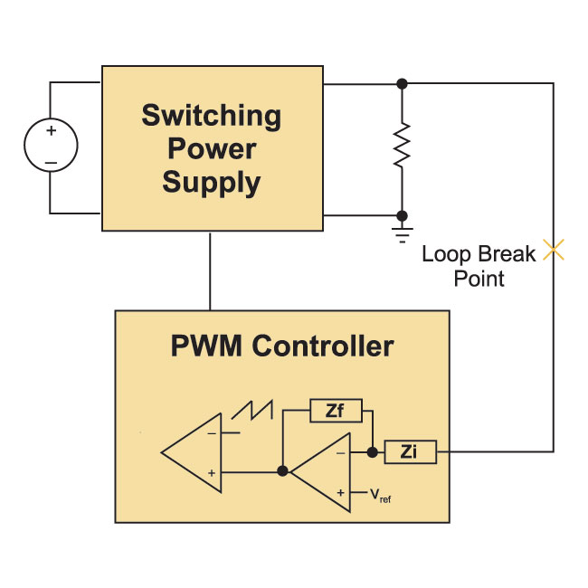
Figure 1: Power Supply with Feedback Loop.
Fig. 2 shows how this could conceptually be measured with the loop physically opened and a signal with dc offset injected into the compensator.

Figure 2: Open Loop Gain Measurement with the Loop Physically Broken.
There are two problems with trying to measure the loop gain in this way. First, with a high gain feedback amplifier, it is impossible systems to apply exactly the right dc offset to the injected signal to prevent the error amplifier from saturating.
Second, the gain of the loop changes by many orders of magnitude over the full frequency range, and the size of the injected signal with this measurement technique would also need to change by the same amount to keep perturbation signals relatively constant.
Breaking the Loop with the Injection Signal
Fig. 3 shows how we overcome the measurement problems for a high loop gain. In this circuit, a 20 ohm resistor is inserted into the feedback loop from the output of the power supply into the error amplifier. The value of this resistor is not critical, but it should be low compared to the feedback resistors of the compensation network.
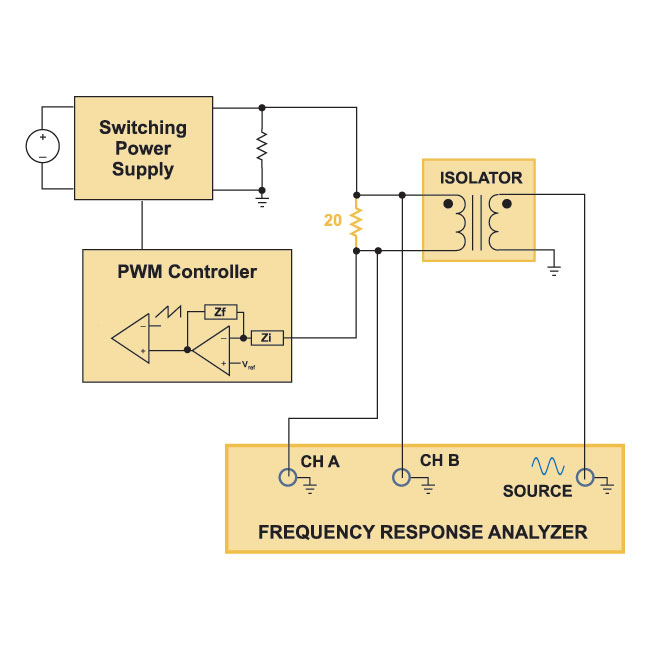
Figure 3: AP300 Open Loop Gain Measurement with the Loop Electronically Broken.
The test voltage is injected differentially across the resistor via a transformer isolator as shown. The transformer should have a reasonably flat response over the range that the loop will be measured. This is typically from 10 Hz up to beyond the switching frequency. For power factor correction circuits, it may be necessary to go as low as 0.1 Hz. An upper band of 10 MHz may be needed for high-frequency converters.
With this technique, the loop is kept closed in order to regulate the output voltage, but the voltage impressed across the resistor allows the measurement of the open loop gain. In effect, we are electronically breaking the loop, forcing a difference between the loop input and output signals on either side of the resistor. The loop is only electronically opened at the injection frequency, and kept closed and in regulation at all other frequencies.
The injected signal is set by the frequency response analyzer. However, it is the power supply loop gain that determines the size of the input and output signals. At all times, the injected signal will be the difference between the input and output signals. The signal will be distributed on either side of the injection resistor relative to ground depending on the loop gain of the power supply. This is illustrated below.
Fig. 4 shows a signal (gold) injected across the 20 ohm resistor. Since the loop gain is high at this injection frequency, most of the injected signal appears at the output of the power supply loop, as shown by the red waveform. The input of the loop, shown in green, is attenuated by the value of the loop at that frequency, and very little of the injected signal is seen here. At all times, the vector sum of the input and output signal will equal the injected signal. The relative phase of the two signals is given by the phase of the loop gain at that frequency.
Note that all of the signals in Figs. 4-6 are shown to be free of noise in order to illustrate the concept of loop injection better. In reality, all of these signals would be immersed in noise as discussed in [1].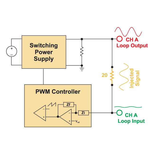
Figure 4: AP300 Loop Injection at Low Frequency, Gain Greater than 0 dB
Fig. 5 shows the signals at a frequency near the crossover frequency of the loop gain. The input and output signals on either side of the injection resistor are now approximately equal, and the phase shift between them gives the phase of the loop gain at crossover.
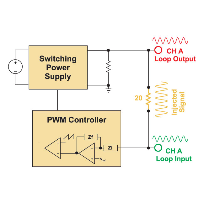
Figure 5: AP300 Loop Injection at Medium Frequency with Gain about 0 dB
Fig. 6 shows the signals at high frequencies beyond the crossover frequency of the loop gain. At this frequency, the input signal is large, and the output signal is small, but the vector sum is still equal to the injected frequency.
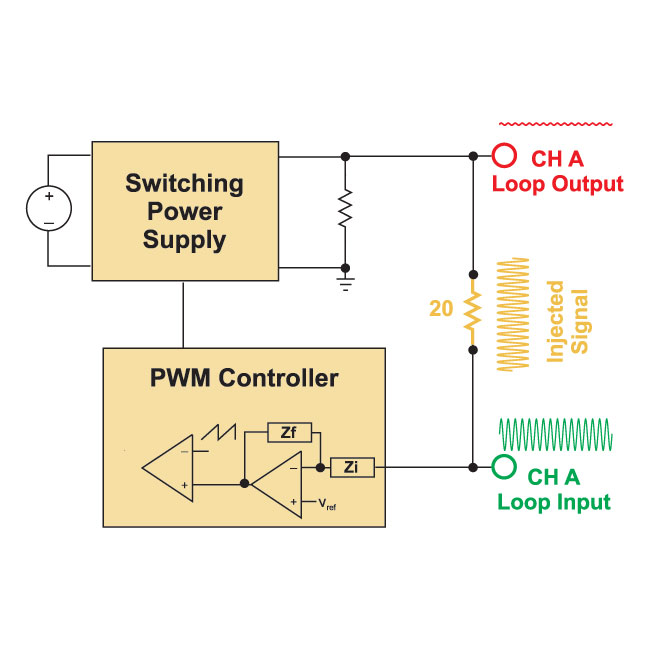
Figure 6: AP300 Loop Injection at High Frequency with Gain Less than 0 dB.
Throughout the frequency range of injection, the output signal can never be bigger than the injected signal. This solves the second problem encountered when trying to inject into the open loop system of Fig. 2: the injected signal does not need to be changed over many orders of magnitude to keep the perturbation signal sizes constant. It still requires adjustment with frequency in most cases for optimal measurements. In the next article of this series, the size of the injected signal and its effect on loop measurement will be considered.
Summary
Loop gain is an essential measurement on all switching power supplies since it will provide information of stability, closed-loop performance, long-term ruggedness of the control, and a sensitive measure of many parts involved in the power supply construction. This article describes the industry-standard technique for injecting into a power supply loop for proper measurements.