


Introduction
In this article, Dr. Ridley continues the topic of frequency response measurements for switching power supplies. This seventh article discusses the approach of trying to use step-load testing to estimate stability and design the control loop.
Step Load Testing
In the last six articles in this series, the importance of frequency response measurements has been shown. Yet it is still a fact that many power supply designers do not make proper loop gain measurements needed for fast and reliable designs. The reasons are varied—lack of time, knowledge, or budget to purchase the right kind of equipment.
Many old-timers in the industry claim that they can see all the characteristics necessary by just looking at the step-load transient response, and that there is no need to make loop measurements at all. This misconception can often lead to expensive errors in design, long and expensive time delays in product development, and instability in the field.
In these next two articles, we will examine the approach of using step-load responses to see how it does not guarantee proper design of the feedback compensation.
Power Supply Transient Response
If3 a feedback loop has inadequate phase margin, it will result in a system that has complex poles in its transfer functions. There are numerous text books you can read on this topic, relating phase margin of systems to pole locations, but the math involved is beyond the scope of this article. Complex poles can also result from an underdamped system, even without the presence of feedback.
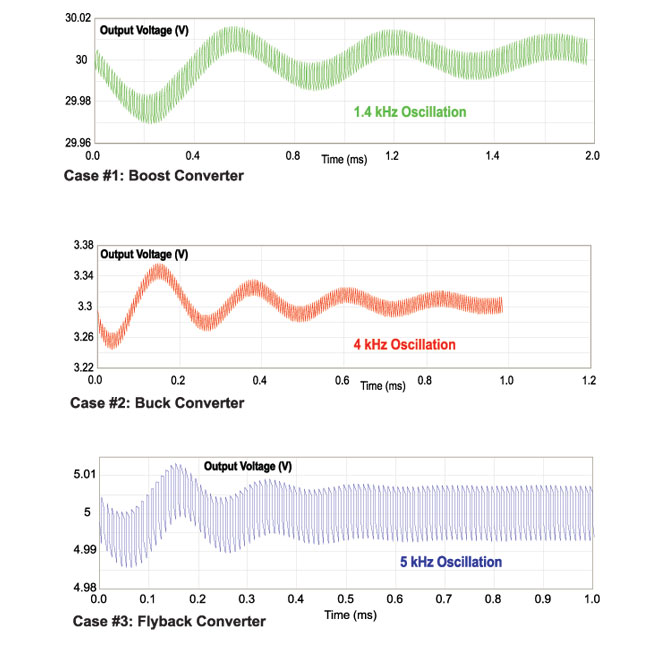
Figure 1: Transient Load Response of Three Different Converters
Figure 1 shows a step load transient response for three different power converters. The waveforms of Figure 1 show damped oscillations with different amplitudes and frequencies. The first converter, a boost supply with current-mode control, has a 1.4 kHz oscillation. The second, a buck converter with voltage-mode control, has a 4 kHz oscillatory response, and the third, a flyback with current-mode, a 5 kHz response.
Proponents of transient response testing will immediately tell you that each of these converters has inadequate phase margin. Transient responses can certainly predict this. At the crossover frequency of the loop, we can even extract the actual phase margin estimate from the duration of the ringing, or from its damping coefficient obtained by observing the waveforms. Unfortunately, while the transient response gives us a single data point of the loop gain (the 0 dB, or crossover point), and information about the phase at that point, it does NOT tell us what to do next.
For each of the first three examples, the solutions to make the loop stable differ. Although the three responses are similar, the strategies for redesigning the loops are different for each of these cases.
In this article, we’ll look at a case where transient response testing might actually work well. Whenever we see oscillations, it is a common approach to reduce the gain of the loop, hoping that the phase margin improves sufficiently to stabilize the system.
Figure 2a shows the initial transient response, with a 1.4 kHz oscillation. A reduction in gain of the loop by a factor of two results in the waveform of Figure 2b. The reduction in gain is sufficient to stabilize the system. But how do we know that the system has been optimized? There is no way to assess this without looking at the loop gain directly.
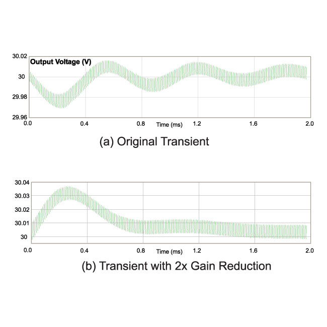
Figure 2: Transient Load Response of Boost Converter (a) Before and (b) After Gain Reduction.
Looking at the loop gains of Figure 3 gives us much more insight into this simple case. The green curve shows the original gain, the red curve shows the decreased gain. The phase margins at the crossover frequencies give us the characteristic transient response. For the red curve, looking at both lower and higher frequencies, we can see that the loop is closer to optimum. The gain decreases uniformly with about a -20 dB slope after the crossover, and at the same time, the phase drops quickly. This is indicative of a system with a RHP zero, and there is little we can do to change the compensation for this system.
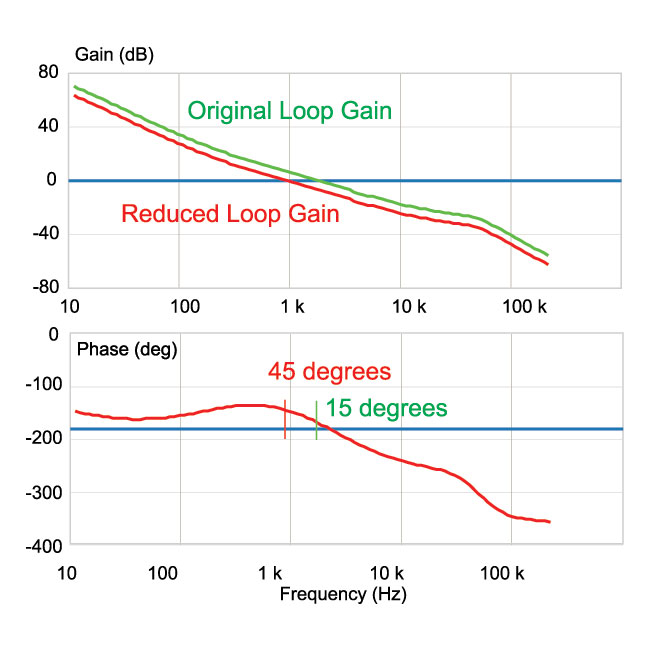
Figure 3: Loop Gain and Phase of the Boost Converter.
The value of looking at the loop gain directly is that we get full information at all frequencies, not just the crossover frequency. In this case, we see that the gain at frequencies below the crossover increase to a high level. This provides optimum noise rejection at these frequencies, and excellent dc regulation of the output voltage.
Summary
Step-load testing can give information about stability, but no direct guidance on how to correct the system. In the first example given in this article, a simple reduction in gain is sufficient to stabilize the system, and measurement of the loop gain shows that this is a reasonable approach. In the next article, it will be shown that a reduction of gain does not fix the stability issue, and the step-load testing cannot shed any light on how to proceed with a proper design.
Some researchers have also suggested that output impedance measurements contain all of the information needed to assess stability of a power supply, but this is simple not true. It has always been necessary to break the loop of a power supply to extract all of the information about the loop stability.