Nonivasive loop gain approximation from output impedance measurements.
Designing noise filters on the output of power supplies, and using proper probing techniques to measure low levels of noise.
For the first time, we provide accurate simulation models for production magnetics. Losses can be simulated for any topology and waveforms.
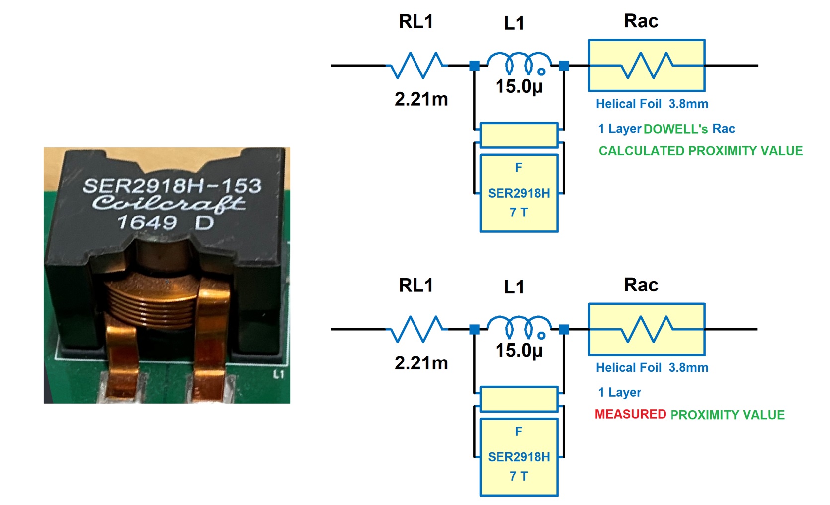
Advanced LTspice circuit models for a helical-foil inductor. Circuit simulation closely matches measured results.
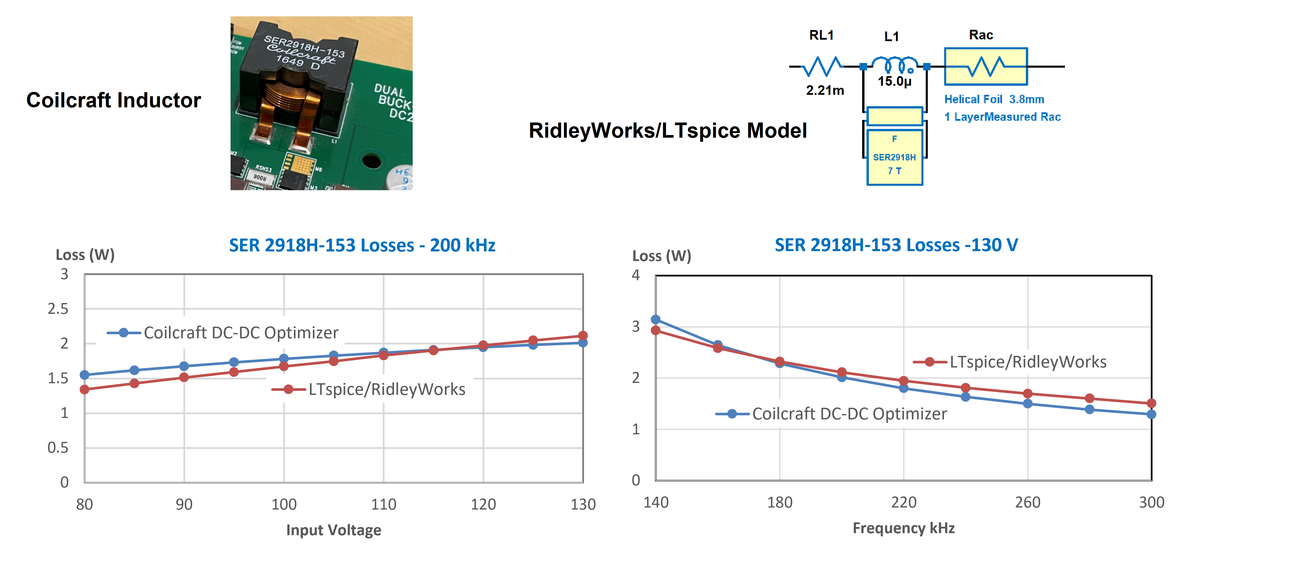
Advanced LTspice circuit models for a helical-foil inductor. Lab measurements of ac resistance capture gap loss and provide accurate results.
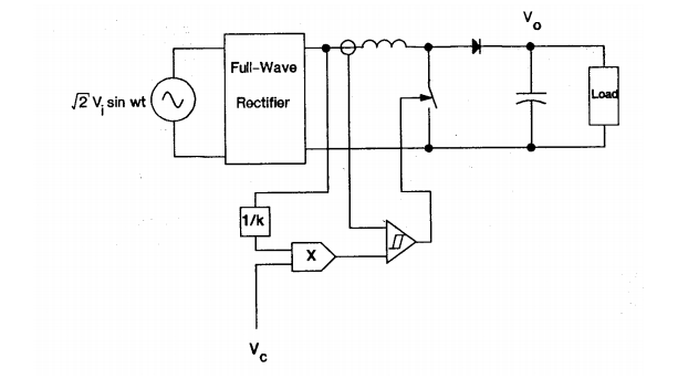
Average Small-Signal Analysis of the boost power factor correction circuit. Originally published 1987 in a VPEC Seminar.
Part I: Learn how to emulate the RidleyBox and AP310 Analyzers in LTspice®.
Part II: Swept loops in LTspice® provide more accurate and useful results than small-signal models.
Part III: Swept loops in LTspice® can be used for the LLC converter where no small-signal model exists.
Compare the RidleyBox Performance for frequency response measurements
50 Years ago, Dr. Middlebrook, showed how the impedance of the input filter will interact with a switching power supply to cause instability. Dr. Ridley shows a new way to control the input filter to make the system stable.
In this article, we will talk about practical design techniques for the most commonly used snubber and clamp circuits for the flyback converter.
Middlebrook's original 1976 paper on input filter interactions. Make sure you design your filter properly to avoid interactions with your switching power supply.
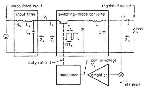
S.S. Kelkar's original 1982 dissertation on feedforward control. This is the first known attempt at controlling the input filter with the converter cell.
The design of the LLC converter is simple and straightforward when using RidleyWorks. No equations are needed, and the design process becomes a pleasure for the engineer rather than a chore.
This unique presentation is by our guest speaker Nicola Rosano. The complex process of dual active bridge converter design is greatly simplified with the application of standardized curves combined with power and frequency scaling concepts.
This early report shows impressively detailed and complex application of Dowell's equations. Chapters 1-4 of the work.
Only 1% of engineers will ever attempt to use this work - will you be one of them? For the other 99%, RidleyWorks does all the hard work for you.
Small die size makes IGBTs competitive in high frequency conversion.
In this two-hour webinar, we demonstrate hands-on why the measurement of Bode plots is one of the most important lab skills you can learn.
Episode 1 of Dr. Vorpérian's landmark lecture series on meaningful circuit analysis (includes pdf handout).
Episode 2 of Dr. Vorpérian's landmark lecture series on meaningful circuit analysis (includes pdf handout).
Episode 3 of Dr. Vorpérian's landmark lecture series on meaningful circuit analysis (includes pdf handout).
Episode 4 of Dr. Vorpérian's landmark lecture series on meaningful circuit analysis (includes pdf handout).
Episode 5 of Dr. Vorpérian's landmark lecture series on meaningful circuit analysis (includes pdf handout).
This unique presentation is by our guest speaker Nicola Rosano. The complex process of LLC converter design becomes very straightforward with the application of standardized curves combined with power and frequency scaling concepts.
In this groundbreaking webinar, Dr. Ridley demonstrates circuit models for core loss that provide loss estimations regardless of waveform. The models provide better worst-case analysis than the original data.
This is an open discussion without any formal presentation from Dr. Ridley. Ask any questions you like about power electronics, history, frequency response, topologies, technology, people, or the past and future of our field.
In this webinar Dr. Ridley shows you how to Design, Build, and Test a Flyback Transformer. We had the ambitious plan to actually build the transformer live during the webinar.
Dr. Ridley tackles the advanced topic of magnetics winding losses. He shows how to reduce complex analytical expressions to straightforward circuit models.
Design and Build a Current Mode Controller in One Hour and learn the 7 secrets of current-mode control
In this webinar, we will do live a demonstration in hardware of measuring a power stage, designing the compensator, and measuring the resulting loop gain and closed-loop responses.
Dr. Ridley's webinar on voltage and current mode control. Get the definitive answer on which you should be using.
In this webinar we will go deep into the design of a converter and many of the aspects that need to be considered.
Performance comparisons of different Injection Isolators. The results will surprise you!
In This video Dr. Ray Ridley talks about Magnetics Essentials
In This video Dr. Ray Ridley talks about the link between RidleyWorks and PSIM
The ZVS full bridge converter can be enhanced greatly by implementing an active snubber on the secondary side of the transformer.
In this article, we have all of the Power Supply Design Center posts from Facebook, archived by Bob Gudgel.
The standardized curves of Dowell’s equations are a superb tool for designing better high-frequency magnetics. A careful balance of layer count and wire or foil count is needed to reach an optimum design.
Very high frequency quasi-resonant converters can benefit from current mode control. Different techniques are used to generate clean waveforms at up to 10 MHz.
This custom-designed comic strip is for all the electrical engineers who are suddenly working from home.
In 2005, all of the major car manufacturers gave up on their electric programs. They were jolted awake again by Tesla who commercialized the TZero technology. You can also read about why the hydrogen economy is a non-starter.
One equation governs the saturation of a transformer, but the leakage inductance provides strong direction to a design.
A provocative talk from Dr. Alex Lidow on the "Death of Silicon"
As with inductors, the design of a transformer is governed by a single design equation. Obey this, and the path to creation of new designs is clear
Inductor manufacturers have made great progress in the families of standard parts. The selection of off-the-shelf parts in this category have increased dramatically in the past 10 years.
Updated version of Dr. Ridley's definitive Current-Mode Control Book
Dr. Ray Ridley continues his discussion on the ONE design equation.
Dr. Ray Ridley discusses his introduction into Power Electronics. An early foray into design optimization software revealed a curious fact about magnetics design - there is only ONE design equation that must be obeyed.
What do you need to build good magnetics? A PhD, or practical experience?
Magnetics represent the most ancient of technologies used in modern electronics systems.
This article gives an example of how profound proximity effects can be.
Dr. Vorperian's hand-written analysis of the tightly-coupled sepic converter.
Dr. Vorperian's analysis of the tightly-coupled sepic converter.
A linear circuit model is derived which will show complex proximity effect losses for arbitrary waveforms.
The competition between hydrogen and electric cars is not even close.
A circuit for producing the output voltage you need from high ac line voltages.
The complete analysis of the Sepic converter – the only place where this can be found. By Dr. Vorpérian.
How to analyze the low-frequency plant characteristics of a PFC circuit.
Proximity Loss in Magnetics Windings.
The first-ever proper analysis of the popular TL431 controller.
Proximity effects show the difference between off-the-shelf designs and custom designs.
Vorpérian’s fractal circuits accurately model the frequency dependence of core loss.
A simple and accurate summary of current mode modelling.
A look at the power systems on the ISS.
Vorpérian’s amazing ripple theorem generates ripple currents and voltages from the small-signal switch model.
Characterize your magnetics properly to guarantee quality parts.
The hidden price of outsourcing is an abandonment of valuable IP.
Useful techniques for accurately determining junction temperatures of your semiconductor devices.
The correct modulator gain is confirmed by experiment. Different analysis results are completely resolved when choosing the right modulator gain.
The right way to drive you power circuit mosfets for safety and ruggedness.
Summarizing the main features of the Sepic control characteristics.
There are many causes for apparent instability in a controller, not just a lack of phase margin in the loop.
A core loss modeling paper from Chris Oliver of Micrometals.
The effects of digital control on loop design.
Kevin Parmenter talks about the trade-off between cost saving and quality.
The Ridley-Nace model improves accuracy over wide range of core usage.
The Tzero car from ac propulsion set the stage for Tesla and other electric car companies.
Frequency response measurements for a wide range of applications.
Papers from MIT and others indicate a current loop gain of infinity under all conditions, clearly an impossibility according to Nyquist.
Dr. Lee's early papers indicated a current loop crossover approaching infinity at D=0.5, violating Nyquist priciples by a large margin.
Dr. Middlebrook's early paper on current mode indicated a current loop crossover above half the switching frequency, violating Nyquist priciples.
Confusion and errors in calculating the current modulator loop gain are resolved in this series.
Calculating the difference between sinewave and triangle wave excitation shows that sinewave measurements are sufficient for loss calculations.
Improved formulas for magnetics core loss with duty cycle effects.
Improved formulas for calculating magnetics core loss.
PSRR becomes a major problem with poorly-designed control loops.
Many things can go wrong in the design and production of power supply magnetics.
Choosing the right foil thickness affects total winding dissipation.
Inductors made with helical foil windings.
Practical control measurements for the Cuk converter.
Measuring the Sepic converter control transfer function with current-mode control.
Control measurements for the Sepic converter with coupled inductors.
How the point-of-load boost converter control characteristics interact strongly with the input capacitor.
Control measurements for the Sepic converter.
Why Nyquist diagrams are not a very practical measurement.
How to read the critical regions of a loop gain and phase measurement.
Survey results on the causes of power supply failures due to magnetics.
Survey results on the causes of power supply failures due to capacitors.
Survey results on the causes of power supply failures due to semiconductors.
Point-of-load converters are prone to unusual results when considering the input filter design with low value capacitors.
Point-of-load converter loops need to measured as they push the state-of-the-art in crossover frequencies.
How to design snubbers when you don't know the inductance causing the ringing.
Using the switch model to analyze the tapped boost converter.
A review of Vorperian's PWM switch model which completely changed the task of converter modeling.
Flyback converter control and loop gain testing.
Flyback design transformer and full power testing.
Flyback input rectifier and transformer design.
Flyback design bias and control circuit testing with high voltage.
Flyback design specifications and architecture.
Why only one injection isolator is needed for all measurements.
What happens when the input filter is poorly designed.
Measuring input filter output impedance.
The proper place to apply Middlebrook's stability criteria for input filters.
The relationship between loop gain and input impedance
The relationship between loop gain and audiosusceptibility PSRR
The relationship between loop gain and output impedance
How to improve manual impedance measurements with a good signal source.
How to measure your magnetics properly with a minimum of test equipment.
Both hardware testing and simulation are essential to understanding power supply designs.
How to wind a flyback primary for the best possible performance.
How to arrange the components of your second-stage output filter for optimum performance.
Loop design and measurement for the five-output forward converter.
Control predictions and measurement of the five-output forward converter.
Cross-regulation characteristics of the five-output forward converter.
Designing custom magnetics for three- and five-output forward converters.
Desiging current transformers for fast sensing on the forward converter.
Making essential measurements on high frequency power transformers.
PCB layout rules for use of ground and other planes.
PCB layout procedures including current loops.
PCB layout procedures including voltage spacing.
PCB layout for the forward converter control chip.
Testing and development schedule for the forward converter.
Initial full-power testing of the forward converter.
Design and testing of rugged current limiting for the forward converter.
Snubber and clamp design for a forward converter.
Magnetics and inductor testing in the forward converter.
Further testing on the forward converter.
Initial testing on a forward converter design.
Introduction to the series on how to design a forward converter.
How to safely test your switching power supplies.
How to select the size of the inductor for a buck converter.
Further examples of why step-load testing will not give you the design information that you need.
Why step-load testing will not give you the design information that you need.
Concepts of gain margin, phase margin, and relative stability.
Injecting the right signal size is crucial for accurate loop gain measurements.
Measuring the open-loop gain of a system while the loop is kept closed for regulation.
Important measurements to make for a power supply design and analysis.
Single-frequency injection and measurement is used to analyze and test power supplies.
The needed frequency range of power supply design and analysis is explored.
The main switch current of a converter should always be measured to ensure that the converter is operating properly.
The "simple" flyback converter exhibits very complex ringing waveforms due to circuit parasitics.
Free downloadable software shows the characteristics of the current-mode buck-boost (flyback) converter.
Free downloadable software shows the characteristics of the current-mode boost converter.
Free downloadable software shows the characteristics of the voltage-mode boost converter.
Free downloadable software shows the characteristics of the current-mode buck converter.
Free downloadable software shows the characteristics of the voltage-mode buck converter.
A short summary of the important features of current-mode control, and links to the definitive free book on the topic.
How inaccurate current limiting can cause problems in low-power flyback designs.
Design equations and analysis of the most commonly-used RCD clamp circuit used for the popular flyback converter.
For most power supply applications, a handful of topologies continue to be used after more than 30 years. Simplicity and ruggedness keep these circuits relevant today.
You can analyze your power supply filter quickly and easily with free downloadable software. This allows you to check for filter impedance interactions, attenuation, and proper damping.
Switching power supplies remain a weak link of most electronic systems and fail more often than they should. The reasons for failure are discussed.
The changing characteristics of the capacitors used in power supplies are examined. They are not as simple as most engineers assume.
Digital power is all the rage now, but don't expect it to shorten your design time, or to eliminate the need for complete optimization of the analog parts of the power supply.
Proximity Loss in Magnetics Windings
How to measure and model high-frequency magnetics for switching power supplies. Essential steps for both custom-designed parts, or purchased components.
Simple and effective gate drive schemes are presented, with some warnings about things that can go wrong.
The Sepic converter dc analysis is presented, showing why this is a popular converter. Beware of the ac characteristics though.
Even the simple buck converter can present very complex and changeable control characteristics when interacting with surrounding components and operating in different modes.
Our worldwide HQ 725 W Ventura BlvdSuite H Camarillo, CA 93010
Phone US: +1 805 504 2212 Phone UK: + 44 (0)1509 276 245 Email: info@ridleyengineering.com
Contact Us
2017 Ridley Engineering, Inc. All rights reserved.