


Why you need only one injection isolator
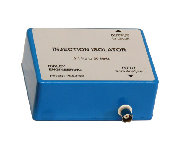
Figure 1: The RIDLEY UNIVERSAL INJECTOR offers extraordinary wideband operation with either large voltage drive, or high current drive.
A Brief History
I have been working with frequency response analyzers for over 30 years. My first introduction was when working on switching power supplies during my undergraduate degree at Boston University. My senior project was to design an offline switching power supply with a 20 kHz sine wave output regulated at 6,000 VAC. During that project, it quickly became apparent that the problems encountered during the design would have to be analyzed in both the frequency domain and the time domain. My first frequency response analyzer in school consisted of a vacuum tube amplifier, function generator, and oscilloscope. All measurements were done manually.
When I graduated in 1981, I went to work at Prime Computer in Massachusetts, designing 1 kW power supplies for computers. I attended Dr. David Middlebrook’s course on structured analog design, and I was eager to try out his loop gain measurement techniques in the lab. This was a very new topic to power supply designers in those days, and most switchers were sent out into the field without any measurements. Of course, many of them were returned later for repair.
At Prime Computer, we used a narrow-band voltmeter from Hewlett Packard. This simple analog machine was capable of putting out a test signal, and measuring a single return signal at that frequency, with a switchable bandwidth. The output was purely analog and visual – a moving coil voltmeter that displayed the size of the measured signal. With a single input channel like this, Dr. Middlebrook taught his course attendees how to measure both gain and phase of a system.
How was this done? With a series of three measurements at each injection frequency. You measured the input signal, the output signal, and the differential injected signal. Then, by applying the cosine rule, you could calculate the phase angle between each of the signals. It was a wonderful teaching tool to learn how these measurements are made, and it gave incredibly clean results. The pure analog measurement technique, and the natural low-pass filtering of the moving coil voltmeter, eliminated almost all spurious measurements. We were lucky at Prime to have computers everywhere to at least speed up the data entry and calculations with very early versions of spreadsheets, but it was very time consuming.
The Next Generation
Then, equipment appeared on the market that automated the process. After the narrow-band voltmeter approach, we purchased another all-analog unit from Bafco – the Bafco 916XH. I remember it well, because I spent many hours in front of its mechanical logarithmic dials.
The Bafco was a great machine in that it had sufficient frequency range for those days, up to 100 kHz, and a massive drive signal of 20 V peak-to-peak. This drive was what sold us on the machine. We were working on high power switchers, and they needed a lot of signal to inject into output impedances, input rails, and the loop. The only problem with the was the lack of a computer interface.
I went to graduate school at Virginia Tech in 1984 and studied power supplies in the group led by Dr. Fred Lee. We had wonderful lab equipment there, including the flagship frequency response analyzer from HP, the HP4194A. This was a great machine, big and reliable, with a price tag equal to a very nice BMW. At the end of the model run, a fully-equipped instrument ran about $65,000.
I got to know this instrument intimately, working with it on a daily basis for my seven-year tenure at Virginia Tech. While it did a superb job, it had numerous drawbacks.
All of the problems described above were solved with the frequency response analyzers from AP Instruments. Their analyzers were designed very specifically for the power supply industry, and it included all of the features needed by power supply designers.
Why do I need an injection isolator?
Figure 2 shows how the loop of a power supply is measured with the AP300 frequency response analyzer. I learned this measurement technique first-hand from Dr. Middlebrook. It requires a transformer to inject differentially into the feedback loop of the power supply. Middlebrook suggested the use of a current probe, driven backwards, to inject into the loop.
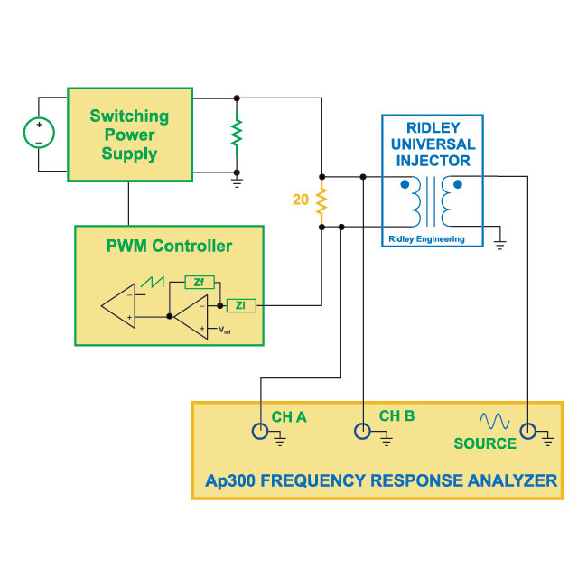
Figure 2: Standard loop injection technique uses a wide-band transformer for signal injection.
While a current probe can inject a signal over a wide frequency range, the injected signal is quite small and inadequate for noisy switching power supplies. Many engineers designed their own transformers to work over the frequency range that they needed. With good transformer design, it was reasonable to expect several decades of operation of the injection transformer. Passive transformers are the technology of choice for this application since they provide a fully isolated signal with no added electronic noise.
How many injection isolators do I need?
The frequency response analyzer from AP Instruments covers the very wide range from 0.01 Hz to 30 MHz. It is necessary to go as low as 0.1 Hz, or less, in order to measure the loop gains of power factor correction circuits, which typically cross over at about 1 Hz. The 30 MHz upper frequency range is critical for characterizing power components, filters, and impedances. An injection isolator is necessary for many of these measurements.
Over the years, students have asked me how many injection isolators are necessary to cover this range. I was always puzzled by this question since I have always only had a single injection isolator for all of my applications. I saw after teaching for many years, that the industry’s range of application was much wider than I expected. It was from this perspective that I created a new product to meet these needs.
At Ridley Engineering, we are now on our fourth generation injection isolator. The first model we created covered the range from about 100 Hz to 15 MHz. Our second product, released about 7 years ago, extended this range from 5 Hz to 15 MHz. The third iteration increased the range, and the present product lowered the output impedance of the device as we will see later.
The latest injection isolator, designed and manufactured by Ridley Engineering, is a truly amazing device. The RIDLEY UNIVERSAL INJECTOR covers the range from 0.1 Hz to 30 MHz. When used with the AP300 analyzer from AP Instruments, it is the only injection isolator you will need. In applications where a substantial current source is needed, it provides unmatched performance.
Voltage Injection Capability of the RIDLEY UNIVERSAL INJECTOR
When injecting into the loop of a power supply, we want to be able to provide a strong signal across the entire frequency range. It is not essential that the signal be perfectly flat, and in many cases, we deliberately adjust the size to avoid overdriving electronic components in the feedback loop. For an injector to be truly universal, it must be capable of a sizeable signal over a very wide range.
Figure 3 shows the absolute magnitude response of the RIDLEY UNIVERSAL INJECTOR over more than an eight-decade range. When working with the AP300, the output signal is maintained constant at a 1 V rms level (2.8 V peak-to-peak) over the truly amazing frequency range from 0.5 Hz (-3dB point) to 30 MHz. Even at 0.35 Hz, there is still 500 mV of signal (1.4 V peak-to-peak) and at 0.1 Hz, the signal is 150 mV rms (0.42 V peak-to-peak).
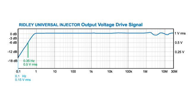
Figure 3: The RIDLEY UNIVERSAL ISOLATOR features an extraordinarily wide frequency range with large output voltage signal
Current Injection Capability of the RIDLEY UNIVERSAL INJECTOR
The RIDLEY UNIVERSAL INJECTOR is obviously adequate for voltage injection into control systems. However, sometimes we need to inject current into a system, as shown in Figure 4. The schematic of Figure 4 is a circuit that we have used in our power supply design courses over the last 11 years to measure the output impedance of a power supply.
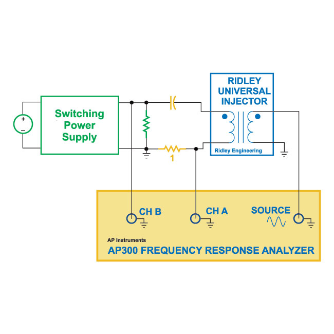
measuring output impedance current must be injected into the output terminals of the power supply.
The output signal from the analyzer passes through the RIDLEY UNIVERSAL INJECTOR , which is then connected with a dc blocking capacitor and 1 ohm sense resistor to the output of the power supply under test. For this test to be successful, we must be able to inject a substantial current into the power supply
Figure 5 shows the current drive capability of the RIDLEY UNIVERSAL INJECTOR . A very substantial 200 mA rms (560 mA peak-to-peak) is provided from 1.5 Hz to beyond 30 MHz. The passively-coupled signal works as both a current source and current sink. At 1.5 Hz, the drive becomes limited by transformer saturation. At 1 Hz, the current signal is reduce to 140 mA rms (395 mA peak-to-peak).
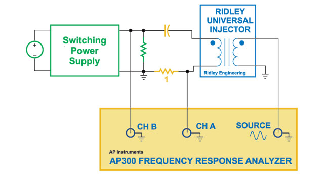
Figure 5: The RIDLEY UNIVERSAL ISOLATOR is designed with low output impedance to drive substantial current over a wide frequency range.
The impressive drive capability of the RIDLEY UNIVERSAL INJECTOR is a result of advanced transformer design, coupled with the output source capability of the AP300 analyzer. The analyzer has a low output impedance of 2 ohms, and is capable of sourcing 0.5 A rms. A power amplifier on the output of this analyzer makes this specification possible. The high drive level of the output 20 V peak-to-peak, allows a step-down turns ration to be used in the RIDLEY UNIVERSAL INJECTOR . This allows both high current and high voltage injection capabilities.
Summary
The RIDLEY UNIVERSAL INJECTOR is an unsurpassed component. When used with the AP300 frequency response analyzer, it can provide a full 1 V rms drive signal into a circuit from 0.5 Hz to 30 MHz, and still has a substantial signal available at 0.1 Hz.
The same universal isolator can provide 200 mA rms current from 1.5 Hz to above 30 MHz. This makes the RIDLEY UNIVERSAL INJECTOR very useful for injecting into the output of power supplies to measure output impedances.
The combination of the impressive voltage and current output ensure that this is the only injection isolator that you need for all of your power supply frequency response measurement challenges.