Free downloadable software shows the characteristics of the voltage-mode buck converter.
Introduction
In this article, Dr. Ridley discusses the problems in comprehending supposedly-simple power electronics circuits. A free piece of analysis software, the first in a series of six, is provided to readers of this column to help them with their power supply design and analysis.
Modeling Power Supplies
The power electronics field is supposedly simple. We have circuits with maybe half a dozen major components in the power stage, and perhaps 20 more parts in the control loop. We use time-tested techniques like breadboards, oscilloscopes, and frequency response analyzers to measure quantities that we are supposed to be able to predict easily with either simulation or design equations.
Despite the apparent simplicity of the field, it rapidly becomes a bewildering place when you design your first products. There are countless books, references, papers and application notes which try to shed some light on the topics that are involved in design.
In teaching power supply design courses for the last 20 years, I constantly face challenges in presenting material that is up-to-date, accurate, interesting, and most importantly, of immediate practical use in the workplace. Engineers attending the courses are expected to immediately increase their productivity at work, and they do. One of the ways that practicality is kept to the forefront of training is by not getting weighed down with excessive equations.
When presenting courses and showing some of the waveforms or transfer functions of converters, I am constantly asked – do you have the equation for that? Some equations are in the notes I present, but most are in the design software that goes with the courses. Of course I have the design equations, but something has always prevented me from writing them all out. First, they are in the form of software equations, and it is a lot of work to extract them from their native format. But, secondly, I do not believe it would do a service to the engineering community to just provide the equations.
It is a strange fact that for the simple set of the three main converters, the buck, boost, and buck-boost (or flyback) there is no single publication that summarizes all of the design and analysis equations in a single place. It has been on my list of things to do for some time now to generate a complete set of equations and publish them as a poster for the basic converters operating in CCM and DCM, and with voltage-mode and current-mode control.
Texas Instruments once provided a wall chart which made some progress toward this, but it had omissions, out-of-date models, or did not cover all of the functions needed by a designer. It is still quite useful if you can find one.
Too Many Equations
I have come to realize that the ultimate set of equations in a concise printed reference won’t happen, and finally last week I was able to put my finger on why. Christophe Basso has just published an update to his Switch-Mode Power Supply book [1] which is highly recommended as a reference to all those involved in power supply design. In this book, he has a thorough review of multiple different modeling techniques over the years, and he presents summaries, including many of the equations needed for design.
There are, in total, over 1300 equations in this book just to cover the basics of operation of our “supposedly simple” converters. Basso’s book is very much a practical volume and the equations in there are necessary to understand this field properly. When you have been in this field for a long time, there is a tendency to forget how much background is really needed to be an effective designer. At some point in your career, you need to go through these equations and understand where they come from, and how they impact your circuit. However, at other times, you want to get to the results as quickly as possible because you are subject to an aggressive schedule.
Fortunately, you don’t have to digest all the equations before you can design a converter. The big advantage of Basso’s book is that it provides Spice models on a CD so you can immediately get to work on your power supply. Understanding the equations can come later.
If you include other advanced aspects of power supplies – resistances that are frequency dependent and nonlinear, multi-output supplies, the intricacies of switching and high frequency snubber networks – the number of equations goes up by an order of magnitude. In fact, it’s worse than that, since many of the expressions for quantities become implicit equations that cannot be solved in a closed form.
Different Equations for the Same Problem
There are other problems with collecting a comprehensive set of equations for our converters. If you compare one reference with another, you will find different answers. Rarely will you find two books with exactly the same expression and notation.
In each analysis, approximations are made to arrive at an answer in a useful form. For example, we might assume the ESR of an output capacitor is always much lower than the dc resistance of the output load on the converter. That will lead to one equation. For some high current supplies, however, the ESR of the capacitor may be comparable, or even bigger than the load resistance, and the assumptions this equation will be invalid in predicting responses accurately.
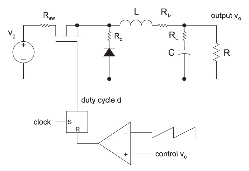
Figure 1: Buck Converter with Parasitic Resistances and Voltage-Mode Control
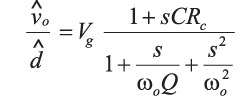
Now let’s look at an example circuit and equation. For the simple buck converter of Figure 1, the equation for the control-to-output transfer function is:

Where

The Q of the filter is given in [5] as

With

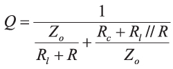
The expression for Q used in the Power 4-5-6 software [2] for the buck converter is:

Equations 3 and 5 for the Q of the circuit are clearly not the same. The first one does not include the series resistance of the diode or switch, and the second one does include these resistances. The second equation makes the assumption that the inductor parasitic resistance is considerably smaller than the load resistance, the first does not.
If you refer to the book by Vorpérian [4], even more effects are incorporated into the modeling, including storage-time delay in the power switch.
Clearly, different levels of complexity are possible, and you can spend a tremendous amount of time analyzing this most straightforward of equations. Then, when you build the real circuit, there will still be some discrepancies in the actual measurements versus predictions.
There are no right and wrong answers to this since none of the published models incorporates everything seen in the real circuit. The damping of the filter resonance is affected by switching losses, inductor core losses, and proximity effect losses in the inductor (this one is very complex – the heating effects occur at the switching frequency, yet the damping is at very low frequency). No publication has been written to try and explain the effect of these phenomena on the transfer functions.
More equations, and more variations from one analysis to another, are created when the buck converter operates in discontinuous-conduction mode (DCM). Vorpérian showed quite rightly that the converter remains second order, and the filter of the converter is heavily damped in this region of operation. The equations for DCM are quite complex, and not included here.
Engineering Design Tools
Basso’s book [1] is very much aimed at the power designer, and also includes a CD of files to run with Spice. If you like to work with Spice, it is highly recommended that you start with these models for your power supplies.
Sometimes you are so under so much pressure that you do not even have time to get Spice running for your circuit, let alone understand the equation derivations. The intent of this series of articles is to provide the working power supply engineer with some design tools that will speed up the design process. To achieve that, downloadable software is available, and will be provided in 6 parts:
Part 1. Buck converter with voltage mode control in CCM and DCM
Part 2. Buck converter with current-mode control in CCM and DCM
Part 3. Boost converter with voltage mode control in CCM and DCM
Part 4. Boost converter with current-mode control in CCM and DCM
Part 5. Flyback converter with voltage mode control in CCM and DCM
Part 6. Flyback converter with current-mode control in CCM and DCM
This software can be found at http://www.ridleyengineering.com/freesoftware.html.
Part 1 – Buck Converter Analysis with Voltage-Mode Control
The buck converter is the simplest of all, with the equations shown above for the control-to-output transfer function in CCM. After you have downloaded the file for the buck converter, you can enter your converter circuit elements, and immediately plot the control transfer functions. You can also vary input voltage and load resistance to see the effect of different operating conditions on the control transfer function.
In CCM, the control function of the buck converter looks like a simple LC filter, with a gain set by the input voltage to the converter. Damping of the filter is affected by the parasitic component resistances of the circuit and the load resistor. The model provided in the software is sufficiently accurate for all practical converters, and you can use it with confidence.
At light loads, the converter will enter DCM, and the characteristic LC filter characteristic will be replaced by a system with a dominant pole, and a second high frequency pole. The software will automatically detect when this happens for your circuit elements.
Summary
As a power supply designer, you have your hands full trying to get a power supply into production. Unless you have a lot of spare time available, don’t get caught up in trying to re-derive equations that vary from paper to paper, or trying to reprogram equations that have already been done before. You will never achieve perfect correlation between modeling and measurements anyway, so make sure your time is well allocated in solving the bigger problems that you may have with making your power supply rugged and reliable.
Make use of the tools that will be available with this column over the coming months, or you Spice simulations of converters that have already been set up by experts in that field [1].
References
- Join our LinkedIn group titled “Power Supply Design Center”. Noncommercial site with over 7000 helpful members with lots of theoretical and practical experience.
- For power supply hands-on training, please sign up for our workshops.
- “Switch-Mode Power Supplies”, Christophe P. Basso, published by McGraw-Hill, 2008.
- “Power 4-5-6 Design Software”
- “A New Small-signal Model for Current-Mode Control”, Raymond B. Ridley,1990 PhD dissertation, free download
- “Fast Analytical Techniques for Electrical & Electronic Circuits”, Vatché Vorpérian, published by Cambridge University Press, 2002.
- “Dynamic analysis of Switching-Mode DC/DC Converters”, A.S. Kislovski, R. Redl, and N.O. Sokal, published by Van Nostrand Reinhold, 1991.


