


Free downloadable software shows the characteristics of the current-mode buck converter.
Introduction
In this article, Dr. Ridley presents a summary of current-mode control for the buck converter. A free piece of analysis software, the second in a series of six, is provided to readers of this column to aid with the analysis of their current-mode buck converters.
Modeling Power Supplies with Current-Mode Control
In the last article, the complications of modeling power circuits were discussed in some detail for a buck converter with voltage-mode control. Even for that simple configuration, the analysis can have different levels of complexity. This will depend on how many parasitic components are included in the analysis, and any assumptions made about their relative values.
We don’t usually use voltage-mode control for rugged converter design. Current-mode control is the preferred approach, implemented as shown in Figure 1.
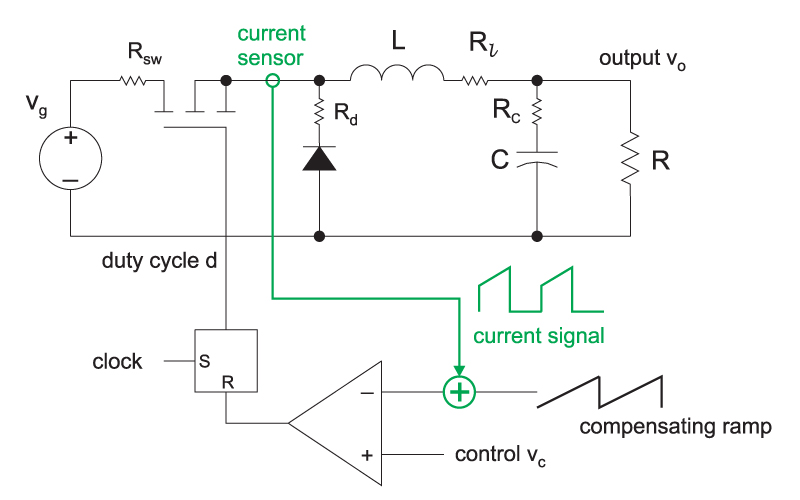
Figure 1: Buck converter with current-mode control. The green components show the current feedback; without these, the control is voltage-mode.
A whole new world of mathematical complexity arises when current-mode control is used for a power supply. Fortunately, the full analysis of current-mode control is completed, and you can download the complete book on the topic from http://www.ridleyengineering.com/freesoftware.html.
The dynamic analysis of current mode involves advanced techniques, including discrete-time and sampled-data modeling. This is essential to arrive at a model which explains all of the phenomena seen with your converter, and which accurately predicts the measured control-to-output response and loop gain of the current-mode converter.
There are several important points to learn from the full analysis of the current-mode converter:
The power stage has a dominant-pole response at low frequencies, determined mainly by the time constant of the output capacitor and load resistor values.
The power stage has an additional pair of complex poles at half the switching frequency which, under certain conditions, will create instability in the current feedback loop.
The resulting transfer function of the power stage is third-order, even though there are only two state variables in the converter. (This apparent anomaly, for control theorists, is caused by the fact that the switching power converter is a nonlinear, time-varying system.)
The second-order double poles at half the switching frequency cannot be ignored, even though they may be well beyond the predicted loop crossover frequency.
The capacitor ESR zero is unchanged by the presence of the current loop feedback.
As explained in reference [1], current-mode control has many advantages. These include elimination of the resonant filter frequency, the ability to current share with multiple power stages, simplified compensation design, and inherent peak current limiting.
Designing with Current-Mode Control
While the analysis of current-mode control is quite complex to read and understand, the design process is quite simple. Much simpler, in fact, than voltage-mode control, and this is one of the reasons that current-mode control is so popular today.
Figure 1 shows the current-mode feedback system. The inductor current, or switch current, is sensed and compared to a voltage reference to set the duty cycle of the converter. A sawtooth ramp may also be added to the signal to stabilize the current loop.
Closing the current loop is straightforward. A current transformer, or sense resistor, is used to generate a voltage signal proportional to the actual current in the switch. The only requirement on the design of this network is that the resulting signal should not exceed the voltage headroom available in the PWM comparator. You do not have to think about the gain of the current loop, or resulting transfer functions at all during this phase of the design.
It is an interesting feature of the current loop that, regardless of how large you make the gain of the current sensing network, the current loop gain remains constant. This is because the PWM modulator gain, which is part of the current loop, is determined by the reciprocal of the slope of the sensed current. The higher the current gain, the lower the gain of the modulator. The two effects exactly cancel each other.
Once the current sense network is selected, you must decide whether you need to add a compensating ramp to the system. This is usually done for converters which will operate at duty cycles above 40%. Further details are given in [1]. Addition of the compensating ramp provides independent control of the PWM modulator gain. This stabilizes the tendency of the current feedback to oscillate at duty cycles approaching 50%.
Buck Converter Current-Mode Software
Software is now available for download that allows you to predict the small-signal response of your buck converter with current-mode control. After entering your power stage values and switching frequency, you can design the current loop parameters of current gain, and compensating ramp value. The software will help you choose the proper values. Once this is done, the transfer function gain and phase of the power stage is plotted for you, and the resulting poles and zeros given.
The software is designed to run under either Excel 2007 or Excel 2003. Make sure when you open the software that the macro features are enabled in order to use the program properly. Please go to www.ridleyengineering.com to download the software.
Summary
As mentioned at the end of the Design Tips in last month’s magazine, you have your hands full trying to get a power supply into production. Trying to understand the intricacies of analysis of current-mode control is a useful thing to do, but most engineers simply don’t have the time with their aggressive development schedules.
The software tool made available with this article will help you design the current loop properly, and give you the analysis of the converter. Remember, however, the results of any power supply transfer functions should always be verified by measurement. Our power systems are frequently dependent on circuit component parasitics that can be unpredictable, and can also be impacted by noise and improper board layout. Experimental verification [2] is an essential step for a rugged design, and should never be omitted.
References
- Join our LinkedIn group titled “Power Supply Design Center”. Noncommercial site with over 7000 helpful members with lots of theoretical and practical experience.
- For power supply hands-on training, please sign up for our workshops.
- “A New Small-signal Model for Current-Mode Control”, Raymond B. Ridley,1990 PhD dissertation, free download
- “Measuring Frequency Response, Tips and Methods”