


Free downloadable software shows the characteristics of the voltage-mode boost converter.
Introduction
In this article, Dr. Ridley presents a summary of the boost converter with voltage-mode control. Free analysis software—the third in a series of six—is provided to readers of this column to aid with the analysis of their voltage-mode boost converters.
Voltage-Mode Boost Converter
The last two articles covered the buck converter in both voltage-mode and current-mode control. The buck is the simplest of all the converters, but as we have seen, the equations can still be very complex when the full range of operation is considered.
The boost converter offers a new set of complications in analysis and characteristics. It can be a challenging converter to stabilize when operating with voltage-mode control as shown in Figure 1.
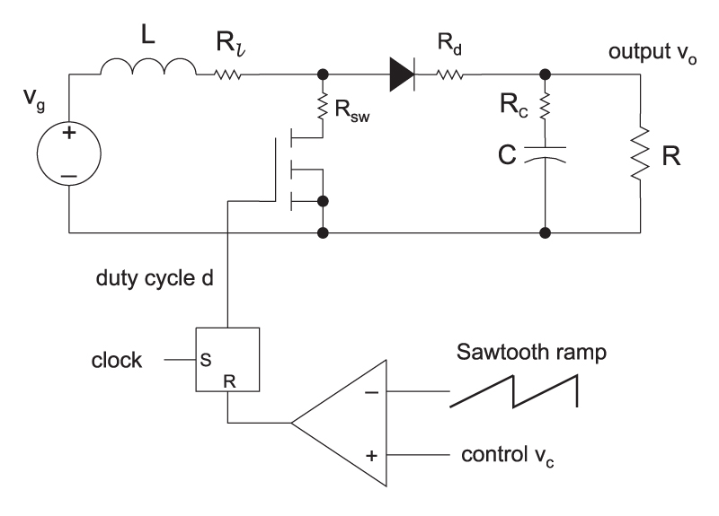
Figure 1: Boost converter with voltage-mode control.
For the boost converter of Figure 1, the equation for the control-to-output transfer function is:
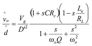
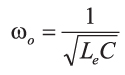
Where the resonant frequency is given by
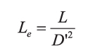
And the equivalent inductance is determined by the duty cycle:
The Q of the filter is a complex combination of the parasitic resistances shown in the circuit, and the load resistance. For this equation, you can refer to either [3] or [5].
Boost Converter Right-Half-Plane Zero
The boost converter adds a new complexity to the control problem – a right-half-plane (RHP) zero. This is caused by the fact that when the boost converter switch is turned on for a longer period of time, the inductor is disconnected from the load for a longer period of time. That means that the output initially drops, even though the control command is trying to make it increase.
Figure 2 shows the effect on the gain and phase of the RHP zero. At heavy loads, the RHP zero frequency is the lowest, and the phase delay is the greatest. At light loads, the RHP zero frequency is higher, and the converter is easier to control.
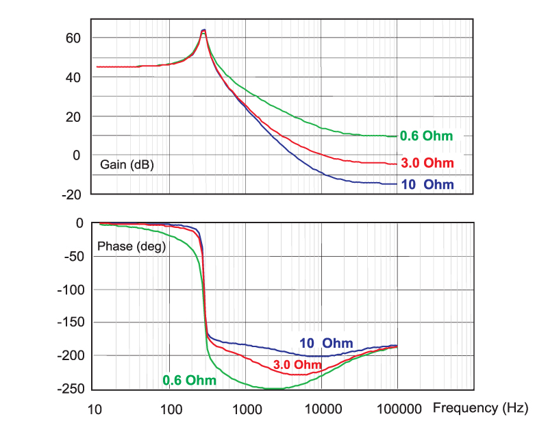
Figure 2: Effect of changing loads on the control characteristic of the boost converter
The operation of the boost converter also causes a shift in the resonant frequency with input voltage, as can be seen from the control equations. Figure 3 shows how the characteristics of the boost converter can vary dramatically with a wide input voltage.
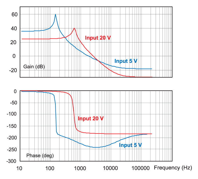
Figure 3: Effect of input line variation on the control characteristic of the boost converter.
The general rule of thumb for converters with RHP zeros is to design at the lowest input line and the maximum load. This causes the lowest value of RHP zero, and the lowest value of resonant frequency. However, when using voltage-mode control, the moving resonant frequency can create problems at different operating points, and the whole range of operation should be carefully checked with both prediction and measurements.
More equations are created when the boost converter operates in discontinuous-conduction mode (DCM). These are not given in this article, but the free software provided for the boost converter will automatically assess which mode of operation your converter is in, and provide the proper transfer function.
Important Characteristics
There are several important points to remember about the boost converter operating in continuous-conduction mode:
There is a double pole at the resonant frequency of the LC filter. The frequency of this double pole will move with the operating point of the converter since it is determined by the equivalent inductance of the circuit, and this is a function of duty cycle. At low line, the resonant frequency has its lowest value.
As with all switching power supplies, there is a zero in the control-to-output transfer function corresponding to the ESR of the output filter capacitor.
The boost converter has a right-half-plane zero which can make control very difficult. This RHP zero is a function of the inductor (smaller is better) and the load resistance (light load is better than heavy load). The bandwidth of the control feedback loop is restricted to about 1/5th the RHP zero frequency.
In discontinuous conduction mode, the resonant frequency of the filter is eliminated from the control characteristic, as predicted by the switch model in [5]. This simplifies the control loop design, but higher power boost converters are usually designed to operate in CCM for efficiency reasons.
Boost Converter Voltage-Mode Software
Software is available for download that allows you to predict the small-signal response of your boost converter with voltage-mode control. After entering your power stage values and switching frequency, the transfer function gain and phase of the power stage is plotted for you, and the resulting poles and zeros given.
The software is designed to run under either Excel 2007 or Excel 2003. Make sure when you open the software that the macro features are enabled in order to use the program properly. Please go to http://www.ridleyengineering.com/freesoftware.htm to download the software.
Summary
The boost converter is an essential topology for stepping up the input voltage, and is applied in many areas of power conversion. This includes dc-dc converters, lighting applications, power factor correction circuits, battery discharging circuits, and many other applications. It is a good topology, but care and time must be taken to properly design the control loop. The inductor should be chosen carefully for a controllable power stage RHP zero characteristic. As with all converters, measurement [2] is essential to ensure a stable and rugged product.
References
- Join our LinkedIn group titled “Power Supply Design Center”. Noncommercial site with over 7000 helpful members with lots of theoretical and practical experience.
- For power supply hands-on training, please sign up for our workshops.
- “A New Small-signal Model for Current-Mode Control”, Raymond B. Ridley,1990 PhD dissertation, free download
- “Measuring Frequency Response, Tips and Methods”
- “Switch-Mode Power Supplies”, Christophe P. Basso, published by McGraw-Hill, 2008.
- “Fast Analytical Techniques for Electrical & Electronic Circuits”, Vatché Vorpérian, published by Cambridge University Press, 2002.