


Free downloadable software shows the characteristics of the current-mode buck-boost (flyback) converter.
Introduction
In this article, Dr. Ridley presents a summary of current-mode control for the buck-boost converter. A free piece of analysis software, the final one in a series of six, is provided to readers of this column to aid with the analysis of their current-mode buck-boost converters.
Modeling Power Supplies with Current-Mode Control
The buck-boost converter (or flyback converter in its isolated version) is the most popular converter for generating low power with multiple output voltage levels. The converter can be run in many different modes – discontinuous conduction mode (DCM), continuous conduction mode(CCM), quasi-resonant mode (DCM with switching at the bottom of the DCM ring wave), and various options of fixed or variable frequency. The choice of operation depends on the power level, the application, and the control chip used.
Regardless of the mode of operation of the power stage, current-mode control is almost always used, as shown in Figure 1. Many designers strive to always keep their converter in DCM in order to avoid some of the complexities of control. This is not necessary if current mode control is used, and keeping the converter DCM under every condition of line and load can create large peak stresses in the semiconductors.
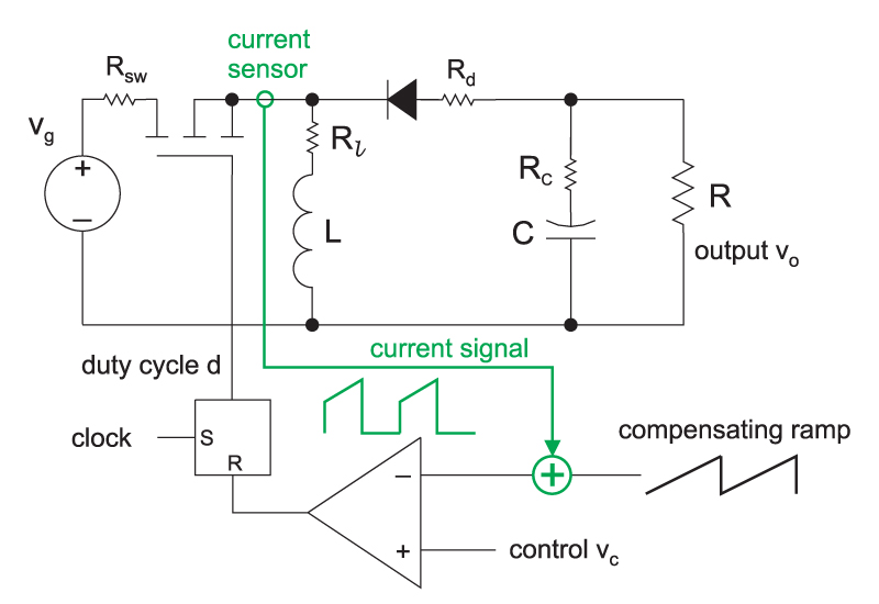
Figure 1: Buck-boost converter with current-mode control. The green components show the current feedback; without these, the control is voltage-mode.
While it is an intuitive control scheme, the proper analysis of current mode control is complex. The dynamic analysis of current mode involves advanced techniques, including discrete-time and sampled-data modeling. This is essential to arrive at a model which explains all of the phenomena seen with your converter, and which accurately predicts the measured control-to-output response and loop gain of the current-mode converter. The full analysis of current-mode control can be downloaded from www.ridleyengineering.com.
Figure 2 shows a plot of the control characteristics of the buck-boost converter in both DCM and CCM. Notice that these characteristics do not change very much at low frequencies, making control optimization straightforward for converters that must operate in both regions.
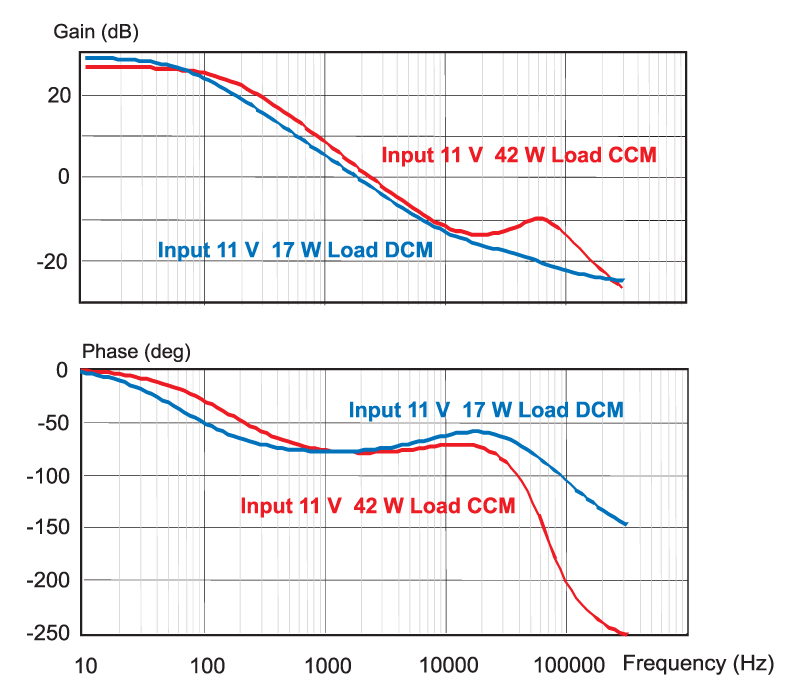
Figure 2: Response of the buck-boost converter with current-mode control in both CCM and DCM operating modes. At lower frequencies, the characteristics do not significantly change, and this is an important advantage of current-mode control.
There are several important points to learn from the full analysis of the current-mode boost converter:
The power stage has a dominant-pole response at low frequencies, determined mainly by the time constant of the output capacitor and load resistor values. This dominant pole response does not vary significantly as the converter moves from DCM to CCM operation, as can be seen in Figure 2.
In CCM, the power stage has an additional pair of complex poles at half the switching frequency which, under certain conditions, will create instability in the current feedback loop. The damping of these complex poles is controlled by the addition of a compensating ramp.
The resulting transfer function of the CCM power stage is third-order, even though there are only two state variables in the converter. (This apparent anomaly, for control theorists, is caused by the fact that the switching power converter is a nonlinear, time-varying system.)
The second-order double poles at half the switching frequency cannot be ignored, even though they may be well beyond the predicted loop crossover frequency.
The capacitor ESR zero is unchanged by the presence of the current loop feedback.
Finally, and most importantly, the current-mode boost converter retains the exact same RHP zero as the voltage-mode converter. However, since the current feedback has eliminated the double poles of the filter resonance, it is not difficult to control this RHP zero effectively.
As explained in reference [1], current-mode control has many advantages. These include elimination of the resonant filter frequency, the ability to current share with multiple power stages, simplified compensation design, and inherent peak current limiting.
Designing with Current-Mode Control
While the analysis of current-mode control is quite complex to understand, the design process is quite simple. Much simpler, in fact, than voltage-mode control, and this is one of the reasons that current-mode control is so popular today.
The switch current of the circuit of Figure 1 is sensed and compared to a voltage reference to set the duty cycle of the converter. A sawtooth ramp is added to the signal to stabilize the current loop. For the buck-boost converter, it is recommended to use a stabilizing ramp at greater than 40% duty cycle in CCM operation.
Closing the current loop is straightforward. A current transformer, or sense resistor, is used to generate a voltage signal proportional to the current in the switch. The only requirement on the design of this network is that the resulting signal should not exceed the voltage headroom available in the PWM comparator. You do not have to think about the gain of the current loop, or resulting transfer functions at all during this phase of the design.
Once the current sense network is selected, you must decide whether you need to add a compensating ramp to the system. Further details of how to add the ramp are given in [1]. Addition of the compensating ramp provides independent control of the PWM modulator gain.
Buck-Boost Converter Current-Mode Software
Software is available for download that allows you to predict the small-signal response of your buck-boost converter with current-mode control. After entering your power stage values and switching frequency, you can design the current loop parameters of current gain, and compensating ramp value. The software will help you choose the proper values. Once this is done, the transfer function gain and phase of the power stage is plotted for you, and the resulting poles and zeros given.
The software is designed to run under either Excel 2007 or later. Make sure when you open the software that the macro features are enabled in order to use the program properly. Please go to www.ridleyengineering.com to download the software.
Summary
If you work with a buck-boost converter, it is advisable to use current-mode control, even if you operate the converter in DCM. While the analysis is complex, the software tool made available with this article will help you design the current loop properly and show the transfer functions of the converter. Remember, however, the results of any power supply transfer functions should always be verified by measurement. Power systems are frequently dependent on circuit component parasitics that can be unpredictable, and can also be impacted by noise and improper board layout. Experimental verification [2] is an essential step for a rugged design, and should never be omitted.
References
- Join our LinkedIn group titled “Power Supply Design Center”. Noncommercial site with over 7000 helpful members with lots of theoretical and practical experience.
- For power supply hands-on training, please sign up for our workshops.
- “A New Small-signal Model for Current-Mode Control”, Raymond B. Ridley,1990 PhD dissertation, free download is available.
- 2. “Measuring Frequency Response, Tips and Methods”