


Choosing the right foil thickness affects total winding dissipation.
Introduction
The performance of foil windings is examined for both transformer and inductor windings in a full-bridge converter. Many factors affect the proper choice of foil gauge when designing for maximum efficiency.
Full-Bridge Power Supply
As power levels are increased and output voltages drop, it is common to have just a few turns in the windings of inductors and transformers. When this happens, standard round wires are usually not the best choice for building magnetic structures, and foil is often used. With a foil winding, the width of the foil can be selected to completely fill the width of the bobbin, making much more efficient use of the space available.
The number of turns on the magnetics determines the number of layers of foil to be used. All that is left to select is the thickness of the foil. In conventional magnetics design, at low frequencies, the window is filled by selecting the appropriate large value needed to do this. However, depending on which winding is being designed, and the current waveform in that winding, this will not always lead to the minimum-loss design.
Figure 1 shows the schematic of a full bridge converter with key component values and input and output specifications.
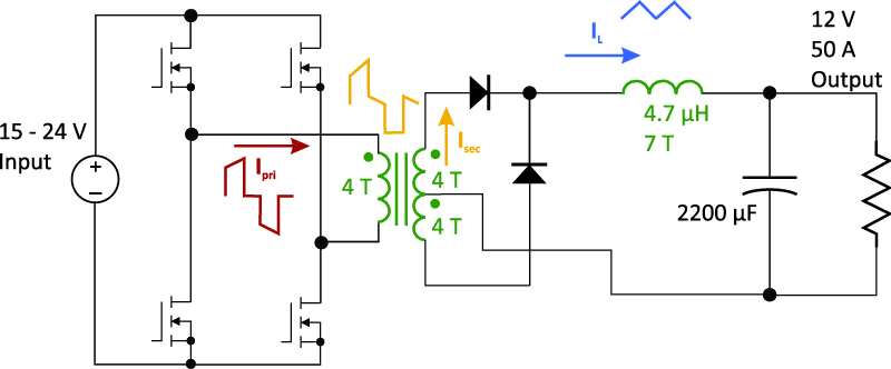
Figure 1: Full-Bridge Power Supply with Input and Output Specifications
Figure 2 shows the windings of the transformer on an EC70 core, with 4 layers of primary foil, and 4 layers of secondary foil filling the entire window. It is unlikely that a high-frequency transformer would be wound with a full window since the leakage inductance resulting would be extremely high, but it is instructional to see what the best thickness of foil would be for minimum loss.
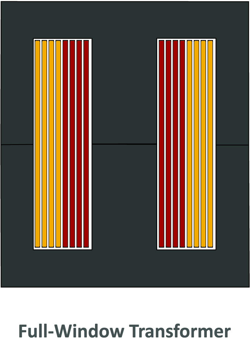
Figure 2: Transformer with Full Window Design
Before deciding on which size foil should be used, we need to know the currents in all of the windings, and the frequency components of the currents. This is best done with simulation, making sure that the converter is in closed-loop steady-state before assessing losses. The fastest simulator for this purpose is POWER 4-5-6 [1] which will also make sure the compensation for the loop is optimized to minimize the simulation time to steady-state.
Full-Bridge Magnetics Current Waveforms
Figure 3 shows the primary current of the full-bridge converter at maximum input line and maximum load. As you can see in this waveform, the primary winding carries no DC current, and the main frequency component is at 50 kHz. There are other small components at odd harmonics of the fundamental frequency as shown in the graph beneath the waveform.
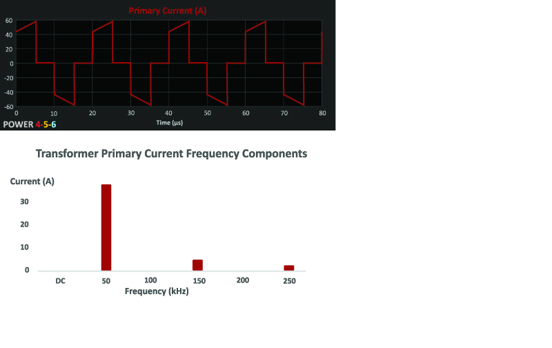
Figure 3: Transformer Primary Current Waveforms and Frequency Components
Figure 4 shows the current in one of the transformer secondary windings. This current is quite different from the primary waveform since there is a center-tapped arrangement on the secondary of the transformer. When one pair of primary switches conducts, the secondary carries the full load current, and when the other pair conducts, there is no current in that secondary. During the off-time of the primary, the two secondaries share the load current equally.
As a result, the secondary windings of the transformer have very different spectral content to the primary winding. Unlike the primary winding, there is a DC offset current equal to half the load current. The main high-frequency component is at 50 kHz, as in the primary, but the secondary has both odd and even harmonics.
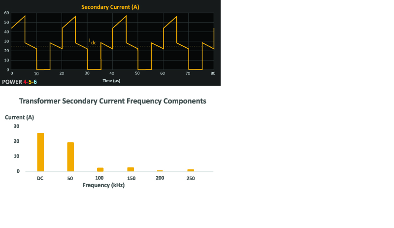
Figure 4: Transformer Secondary Current Waveforms and Frequency Components
Figure 5 shows the current waveform for the output inductor. This current is composed of mainly DC, and another component at twice the primary switching frequency, or 100 kHz.
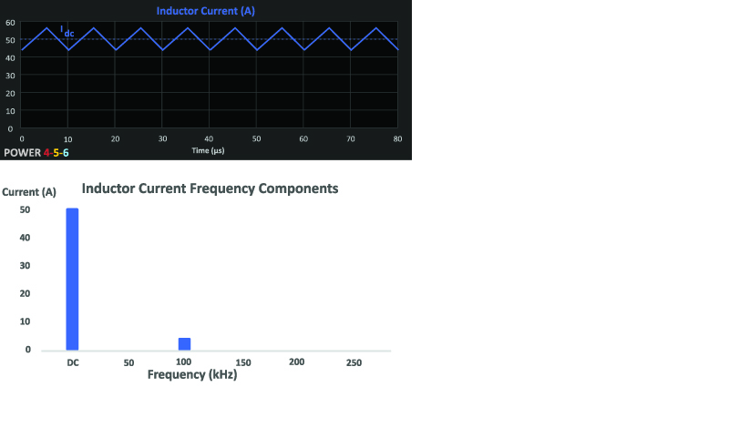
Figure 5: Output Inductor Current Waveforms and Frequency Components
Magnetics Foil Optimization
Since each of the magnetics windings contain different frequency components, the optimal foil thickness for each will be different. Choices will depend on how much dc current is being carried, how much ac current, the dominant frequency, and the number of layers of foil. The choice of the best foil thickness for each of these considerations is determined by the proximity loss analysis for each of the windings. While proximity loss analysis is a powerful tool that has been around for almost 100 years, it is very seldom used by designers since the mathematics is very complex. [2]
More experienced designers refer to curves derived from Dowell’s equation, but the process can be quite tedious. It has been made easily accessible to every designer inside the design program POWER 4-5-6 where the magnetics are analyzed with the simulated circuit waveforms. This is beyond the capability of normal circuit simulation packages.
Figure 6 shows a POWER 4-5-6 screen capture with the analysis breakdown of the inductor winding design. A single click of a button allows you to find the optimal value of foil thickness.
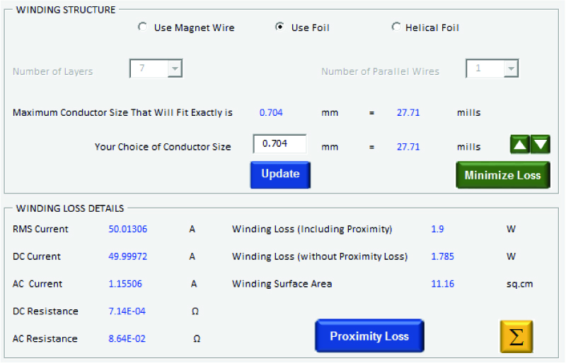
Figure 6: POWER 4-5-6 Winding Optimization Screen
This utility was used to optimize the foil thickness for each of the magnetics windings, and the results are plotted in Figure 7. In this graph, the foil thickness is plotted vs total winding loss (ac proximity loss and dc losses included) for the transformer and the inductor.
Notice that the design minimum is different for each of the windings. For both the primary and the secondary, there is a minimum value of loss, and the losses then climb as the foil thickness goes up.
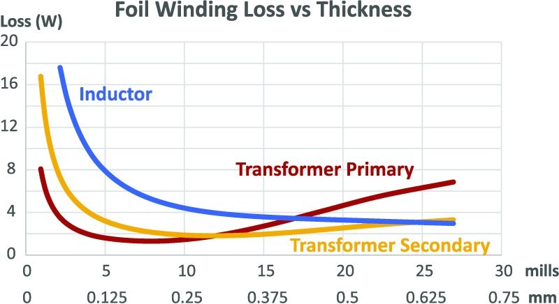
Figure 7: Winding Loss for Magnetics Plotted for Different Foil Thicknesses
Optimum Foil Thickness
Each winding has a different optimal thickness. For the primary, as shown below, the optimal thickness is 0.65 skin depths. This translates into a 7.5 mill winding, or about 0.2 mm.
The secondary winding is about 50% thicker when optimized. This is because there is a significant dc component to the secondary winding. Notice, however, that both primary and secondary are less than one skin depth (at 50 kHz) thick. Figure 8 shows the resulting transformer design, and the window of the bobbin is less than 20% full. For a minimum cost design, this may be fine. However, the performance could be enhanced further by interleaving, adding another primary and secondary set of windings, halving the total loss.
Or, the primary and secondary could be interleaved, alternating one secondary with each primary, and increased in thickness with no loss penalty. Each of the interleaving options will add cost and complexity to the transformer, and will also add to the winding capacitance. Each application may have a different choice of solution. This is one of the reasons that you see so many different transformer designs in our industry.
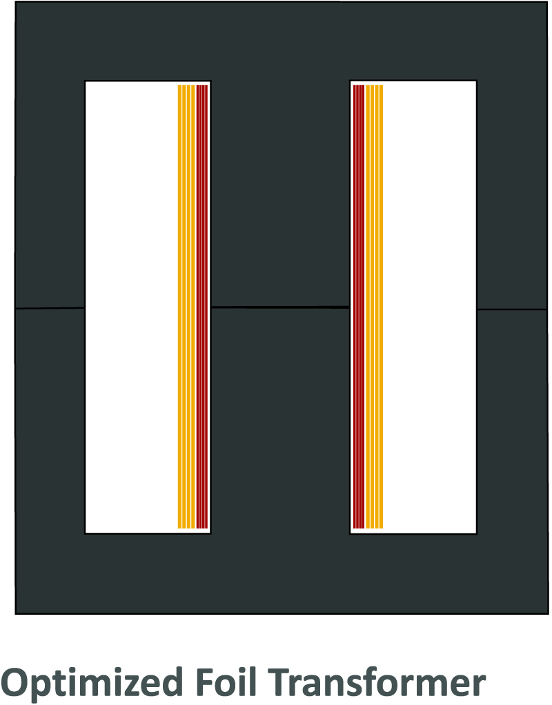
Figure 8: Transformer with Optimal Foil Thickness
The inductor design is quite different from the transformer. Because the current is primarily DC, the thickest foil possible leads to the lowest loss design. This is not always the case for buck-derived converters. It will depend on the specific design of output current ripple, and with a high ripple, the AC losses will climb, and the optimal foil thickness may be less.
Figure 9 shows the final inductor design. Each layer of foil is 0.7 mm thick, or 3.4 skin depths (at 100 kHz).
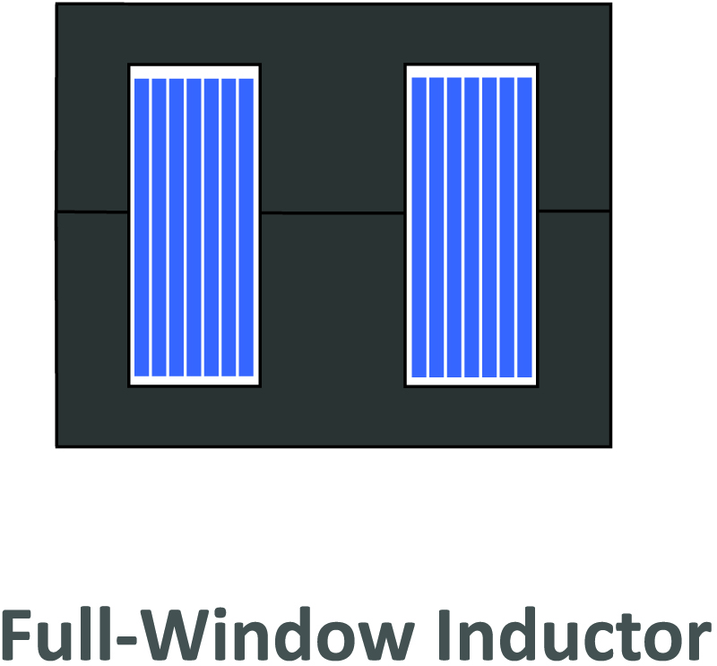
Figure 9: Inductor with Full Window Design on RM12 Core
Summary
When designing foil windings for magnetics, the thickness of the foil is a key design parameter. The lowest loss for a transformer winding is usually given by a fairly thin winding, in the vicinity of the skin depth. The actual value relative to the skin depth of the current flowing will depend upon the frequency components of the currents and the number of layers of winding. An output inductor frequently has an optimal foil thickness which is quite large since most of the current is dc.
It is important to understand the current flowing in each foil winding, and properly apply Dowell’s equations to get the best performance out of your designs.
References
Proximity Loss Calculator in POWER 4-5-6, http://www.ridleyengineering.com/software.html
Inductor proximity loss article, http://www.ridleyengineering.com/images/phocadownload/13%20proximity%20loss.pdf
Ridley Engineering hands-on workshop course notes, http://www.ridleyengineering.com/workshops.html
AP300 Application Notes and Videos, http://www.ridleyengineering.com/analyzer.html
Join our LinkedIn group titled “Power Supply Design Center”. Noncommercial site with over 7000 helpful members with lots of theoretical and practical experience.
See our videos on power supply design at http://www.youtube.com/channel/UC4fShOOg9sg_SIaLAeVq19Q