


Dr. Ray Ridley continues his discussion on the ONE design equation.
ONE Design Equation
In the last article of this series, I introduced one equation that matters for inductor design. This is the equation that you will use when you are creating a custom design from scratch. Please note that we are talking about the design of an inductor, NOT the analysis process. Mathematical structure analysis can be quite involved and is a popular subject for PhD dissertations. You can also read many articles on this topic in our Design Center [1].
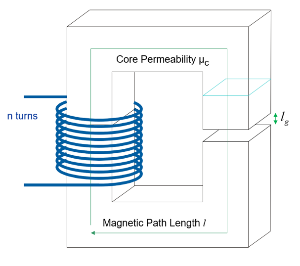
Figure 1: The Basic Constituents of a Custom-Designed Inductor.
The design equation that matters is as follows:
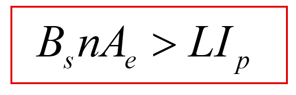
We have arranged this equation with the magnetics variables of core saturation level, number of turns, and core cross-sectional area (minimum) on the left. The electrical engineering variables are on the right, and these are usually determined by the circuit designer through simulation, experience, and personal preferences. We will talk more about this in a future article, since the choices of inductance can vary widely from one designer to another, and from one application to another.
Defining the BEST Inductor
Design engineers think they want the best inductor for an application. But, what does this mean? To the purchasing department, “best” typically means cheapest, and they will work hard to drive the price down. To the electrical engineer, “best” may mean the most efficient for the application. For the packaging engineer, “best” will mean a smaller size. And for the EMI engineer, “best” may mean small capacitance, and minimal stray electromagnetic fields from the part.
Satisfying all these definitions simultaneously is not possible. For every design, there will be a tradeoff between allowable size, heat dissipation, impact on the rest of the circuit design, and cost. This tradeoff will be different for every application, and that is why you will find a very wide range of inductor designs from one power supply to another.
Starting with Arbitrary Choices
Now we come to the heart of the problem – how to start a design? At many companies I work with, there is an almost pathological obsession with finding the equations to be programmed into Mathcad that will provide the “RIGHT” solution to the problem. Which core should you choose? What material? What is the right answer? Many managers feel that if they can see an equation, their engineers must have chosen the proper solution.
But, there is NO single right answer. There are an infinite number of solutions, and the choice of which way to go is arbitrary. I am deliberately being extreme in saying this to make a point – if you want an optimized inductor, stop looking for nonexistent sets of equations and begin exploring engineering options with an unconstrained mind.
There is an important consequence with the ONE design equation above. Let us assume that we have chosen the inductance and the subsequent peak current that results. (more about this will be discussed in future articles – it is not necessarily a simple choice.) The equation implies that you can use a core of ANY size, and if you put enough turns on the core, the inductor will not saturate. That means you can start the design anywhere you wish!
If you are doing this for the first time, just pick a number for the core area. Plug it into the design equation and see how many turns you are going to need to make sure the inductor doesn’t saturate. From that result, it won’t take long to ascertain whether the design is sensible or not. Choosing a number that is too small, for example, will help build our experience base by seeing the impact on losses in the windings or the core. There is usually more to be learned from making a wrong initial choice that starting with a design that will work comfortably. This is the process we encourage in our design workshops – iterate quickly with several different options and you learn quickly.
If you are working with a company that already does custom inductor designs, you may choose just pick a core already being used. This will provide purchasing power that can drive a lower price than a smaller core. It may also fit better with your company’s tooling. There are many factors that will drive the decision, but a single optimizing equation is not one of them.
We will explore the idea of exploiting the design freedom that exists by starting with any size core with examples in later articles. This is also the process that we demonstrate in our design workshops [3].
But now let’s consider how design guidelines that you find in text books or databooks have the unfortunate consequence of removing design freedom and iteration to arrive at a single solution. This is counter-productive to the creative process.
Wire Current-Density Equation
Most data books, text books, and magnetics guides take the same fundamental step in overcomplicating the design process. They search for a single solution that cannot possibly exist for every application. The view is presented that there must be a starting point for the design, and design freedom should not be considered.
For many publications [2], the size of the wire can immediately be locked down according to the arbitrary (but common) current-density equation:
ACu = 500 circular mils/A
Please note that the number 500 is arbitrary. In some books it will be 350, and in others 750. We have deliberately left this expression in one of the absurd units that you will find in many magnetics texts and handbooks (apologies to non-US engineers). A circular mil is the area of a piece of wire that is 1 mil in diameter, that is 0.001” or 25 microns. I don’t like to choose a more sensible unit since I don’t want to encourage people to use this guideline. For all of the magnetics I have worked with, I have never known the current density, but I do know the temperature rise after it has been built and tested.
The equation gives the recommended cross-section of the wire for the rms current in the inductor windings. It seems initially like a reasonable starting point. However, we must ask, where does this equation come from? It is hard to trace the first usage, but ultimately it is derived from the early days of line-frequency magnetics work. Transformers and inductors had hundreds or thousands of turns, and they were massive thermal structures with the windings and cores intimately thermally connected. The recommended current density made sense when the frequency was preselected and the thermal situation was known and well characterized.
However, with high frequency magnetics, we have many compounding factors. Firstly, there may be just a few turns of wire or foil. The thermal situation is profoundly different from multiple layers of wire in a conventional line-frequency inductor. The windings can be in a single layer, multiple layers, on a bobbin, or part of a PCB. The thermal variations are tremendous. So why apply the same design guideline?
And, for most high frequency inductors, there are multiple frequency components to the current waveforms. This leads to uneven current distribution in the wire which is usually considerably thicker than a single skin depth. The current density rule no longer applies, and it is not a good starting point.
Design Tip: Wire Current Density – calculate it if you like, but don’t use it to drive a design. I may never know the current density of the final design. I do, however, want to know how hot it gets.
Window-Area Product Equation
Some texts take a further step in trying to pin down a single “correct” solution by defining a window-area product. This is the product of the area of the core, multiplied by the area of the window available for the winding. This quantity is then used in a design equation based on the power level of the application [2].
Equations like this give the appearance of providing a unique solution and design path. But no two applications can be the same. One of the primary drivers of a design is the cooling of the part. This is never the same from one application to another. Some designs have forced air cooling, and at the other extreme, some magnetics must work in a vacuum with zero air flow. The design process should not be the same for these examples.
Design Tip: Window Area Product – Without full thermal information, it can never be a good guide to design direction.
Gap Length Equation
Some design engineers like to start with a gap length. We ran into this on our LinkedIn group recently with questions asked by new designers in the field [4]. Why? I don’t really know. Perhaps they have a pre-gapped core on hand and don’t want to order another. Regardless, the gap length is not the way to start your design.
However, when you are DONE with a design, you can use an equation to estimate the gap as follows:
lg = µ0n2Ae/L
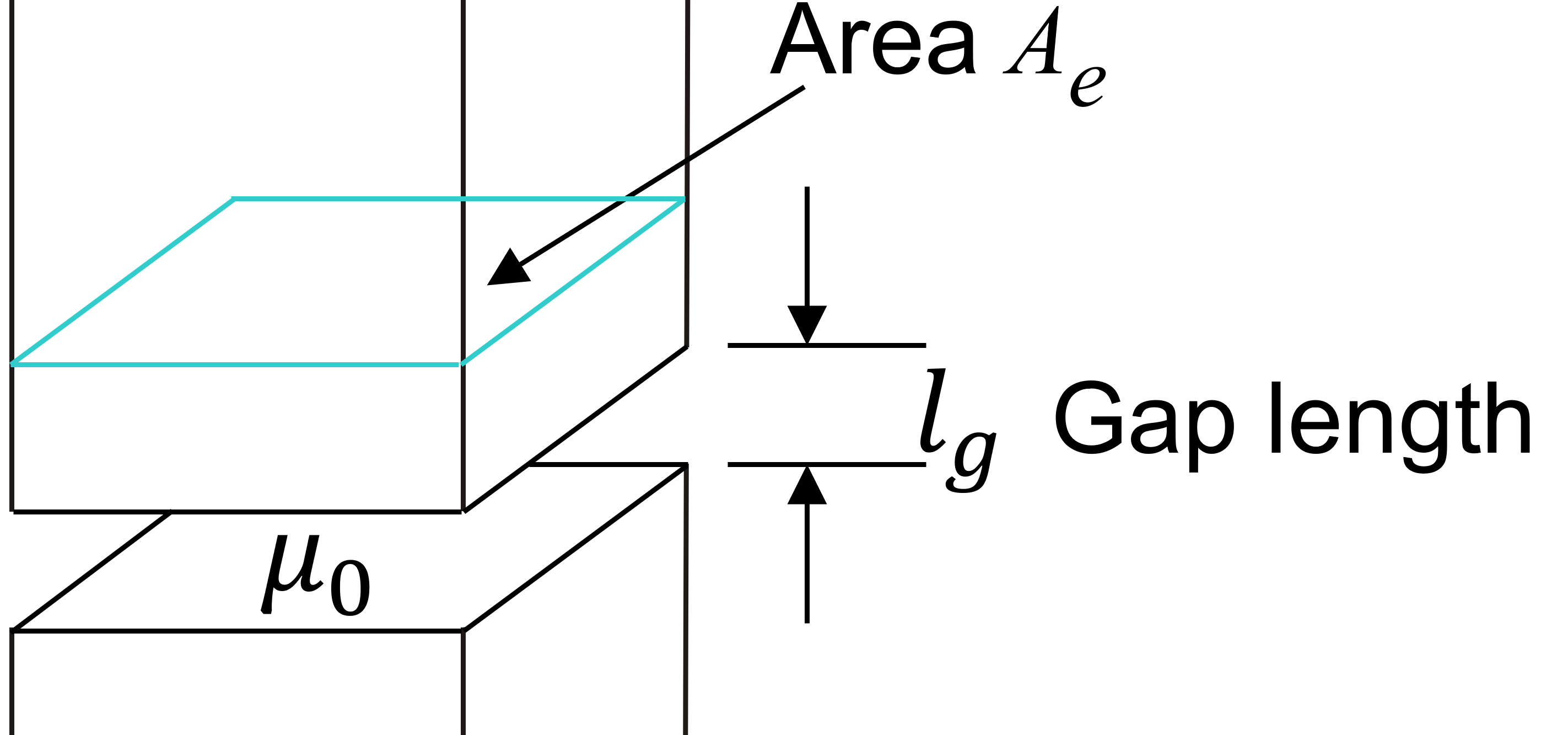
Figure 2: The Simplest Equation Assumes All Energy is Stored in the Gap.
Is this a good and accurate equation? No, not at all! The accuracy will depend on the size of the gap relative to the core total path length, the permeability of the core, and the gap length compared to the dimensions of the core cross section. You can read many papers about fringing fields, and how to find a better equation for the gap.
But, in the end, it doesn’t matter. All equations for gap length will be empirically inaccurate. Don’t worry about this, just gap a finished design until you get the desired value of inductance. That is how inductor manufacturing works. The gap is adjusted to get the inductor with the specified tolerance required.
There are two things that are important about the gap length – one, it should not be too small, or you will be relying on the permeability of the core material, a quantity that can be very variable. And two, it must not be too large, or excessive fringing and EMI will result. In between these two extremes, the actual value of gap is determined empirically.
Design Tip: Gap length equation– Use it to establish upper and lower bounds, but ultimately the gap will be adjusted empirically for the desired result.
Summary
We encourage engineers to experience the freedom in working with just ONE design equation. Try many alternatives, and you will learn quickly through iteration. Most design books constrain designs simply to arrive at a single solution. This discourages creative thought leading to designs that are suboptimal for most applications.
References
[1] Magnetics Design Videos and Articles, Ridley Engineering Design Center.
[2] Mag Inc Design Guide: https://www.mag-inc.com/Design/Design-Guides/Transformer-Design-with-Magnetics-Ferrite-Cores
[3] Learn about proximity losses and magnetics design in our hands-on workshops for power supply design www.ridleyengineering.com/workshops.html (The only hands-on magnetics seminar in the world.
[4] Join our LinkedIn group titled Power Supply Design Center. Noncommercial site with over 7800 experienced and helpful industry experts.
[5] Join our Facebook group titled Power Supply Design Center. Advanced in-depth discussion group for all topics related to power supply design