


Making essential measurements on high frequency power transformers.
Introduction
Dr. Ridley reminds designers of the crucial importance of measuring impedances of every magnetic element that is placed in your power electronics circuit, regardless of the power level. Three impedance measurements versus frequency will speed up your development process, improve the performance of your design, and ensure manufacturing quality.
Magnetic Components
I learned very early in my career as a power designer that transformers and inductors should be characterized versus frequency, regardless of their power level or frequency of operation. This has been part of design procedure for almost 100 years, ever since the use of transformers and motors became widespread.
I have always assumed that all engineers made impedance measurements, but at a recent trip to the PCIM conference in Nuremberg I discovered that most designers do not take the time for this Instead, they rely on just a few static component parameters from their magnetics vendors. Most of the manufacturers of magnetics components also do not make impedance versus frequency measurements since they are usually unaware of the value of such information or they lack the necessary training and equipment to make the measurements.
Transformers and inductors come in many shapes and sizes. Figure 1 shows two magnetic elements – one is a forward transformer for a 60-100 W application and it measures about 3 x 3 cm. This component is dwarfed by the 1500 A inductor for MW applications. Regardless of the power level, the same impedance measurements should be collected for these components.
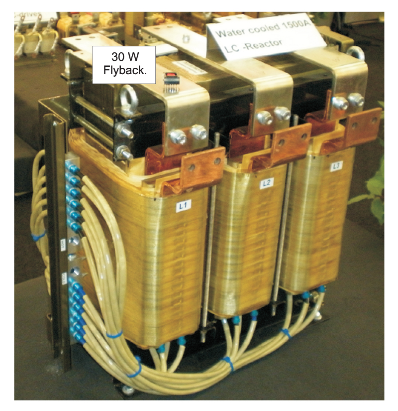
Figure 1: There is a vast range of magnetic components used in power electronics. All of them should be measured across a full frequency range to extract useful design information and important component values.
The equivalent circuit for a two winding power transformer is shown in Figure 2. Notice that many of these components, denoted by a red symbol, are strongly nonlinear. The winding resistances Rp and Rs,vary widely with frequency, sometimes by two orders of magnitude for multilayer windings [5]. The core loss is represented by Rc, and this is a strong function of frequency, excitation level, temperature, and for some materials and applications, the age of the core [3].
The leakage inductance Ll, has significant frequency dependence due to proximity effects. Magnetizing inductance, Lm, will vary depending on core excitation level, and its value can drop drastically during saturation of the core. For ungapped, high-permeability transformers it is also a function of the test excitation level at low frequencies.
The winding capacitances Cp, Cs, and the primary-to-secondary capacitance, Cps, are a function of the surface areas of the windings and the separation presented by the insulation. They can have some variation with frequency, but are usually treated as constant components.
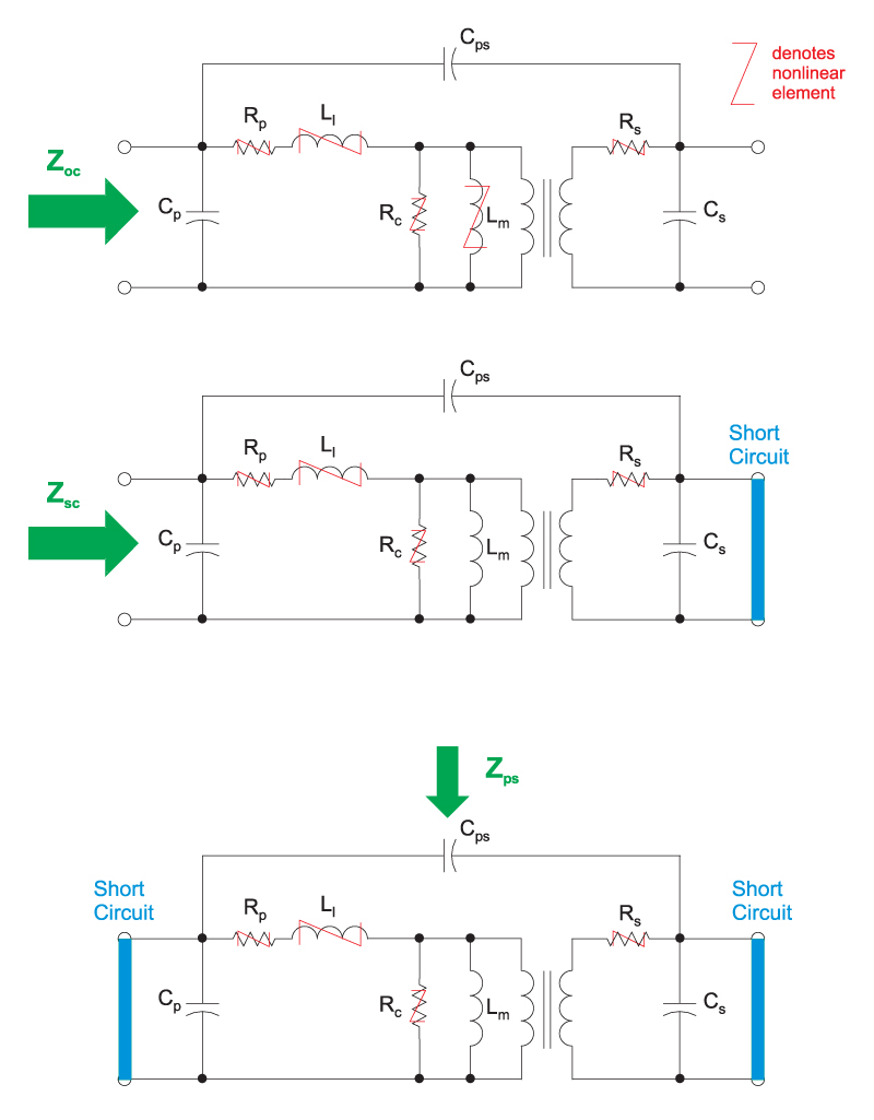
Figure 2: Approximate equivalent circuit of a two-winding power transformer. Three impedances should be measured for this component.
Impedance Measurements and Capacitances
There are three impedances that should be measured for a two-winding transformer. These are the primary impedance with the secondary open, the primary impedance with the secondary shorted, and the primary-to-secondary impedance with both primary and secondary windings shorted. (If you have a step-up transformer, the measurements should be made from the secondary side.) These test setups are shown in Fig. 2, and example measurements are shown in Fig. 3.
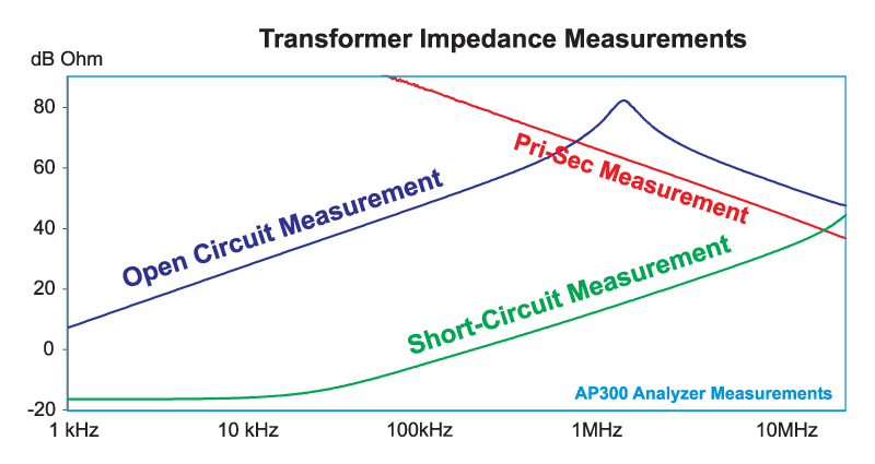
Figure 3: Typical results for the three impedance measurements for a transformer.
From these impedance measurements, we can extract information about the components of the equivalent circuit of Fig. 2, either directly or indirectly. This is very useful for comparing different transformer designs for the same application, or for assessing components provided by different vendors.
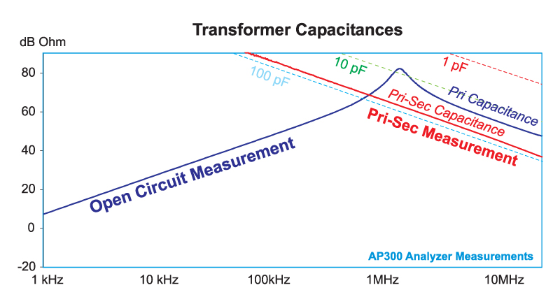
Figure 4: Winding capacitance reference values
Figure 4 shows reference capacitor values for the high-frequency impedances measured for the transformer. It is important that these capacitances are measured only at the frequencies where the impedances are capacitive. Trying to extract the capacitance values at lower frequencies where the components are inductive will result in inaccurate values.
Your measurement setup must be capable of resolving capacitances as small as 1 pF, since this is the normal limit of the range for small switching transformers and inductors. Even small capacitances can have a big effect on waveforms when looking at the switching waveforms in modern high-frequency devices.
It is very important to control the primary-to-secondary capacitance of a transformer since this has a strong impact on the common-mode noise performance of the converter. This is usually a higher value of capacitance than the primary capacitance, and is a function of the insulation distance between primary and secondary.
Resonant Frequency and Inductances
It can be seen from the open-circuit impedance measurement in Fig. 4 that the resonant frequency of the transformer is quite low, less than 2 MHz for a 100 kHz application. This is not a problem for a forward converter. The value of this resonance does not affect the o(peration at all except for the contribution of capacitive current during turn-on. While we do not care about the absolute value of this resonant frequency compared to the switching frequency, it is very important that it stays consistent from one sample to another in order to guarantee manufacturing consistency.)
What is important is that the resonant dip in impedance caused by the leakage inductance and output capacitance is at a high frequency. For this example, the resonant dip cannot be seen since it is higher than the measurement range of 30 MHz.
Figure 5 shows reference values of inductance for the high-frequency impedance measurements. It is recommended to extract values of magnetizing and leakage inductance at frequencies where the components are strongly inductive. For short circuit measurements, this is usually at the switching frequency or higher.
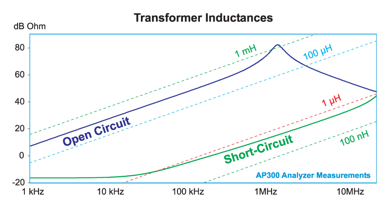
Figure 5: Winding inductance reference values. Notice that the leakage inductance asymptote does not have a 20 dB/decade slope due to a changing inductor value.
The value of the leakage inductance of the transformer is shown in Fig. 6. The inductance for most transformers is frequency-dependent in the range of the switching frequency, as can be seen in this measurement. It is very important that your transformer leakage inductance is specified at a particular frequency if you want to use this parameter to help control manufacturing variation. I frequently see manufacturing documents where the leakage inductance is too loosely specified to be of value in ensuring properly-manufactured parts.
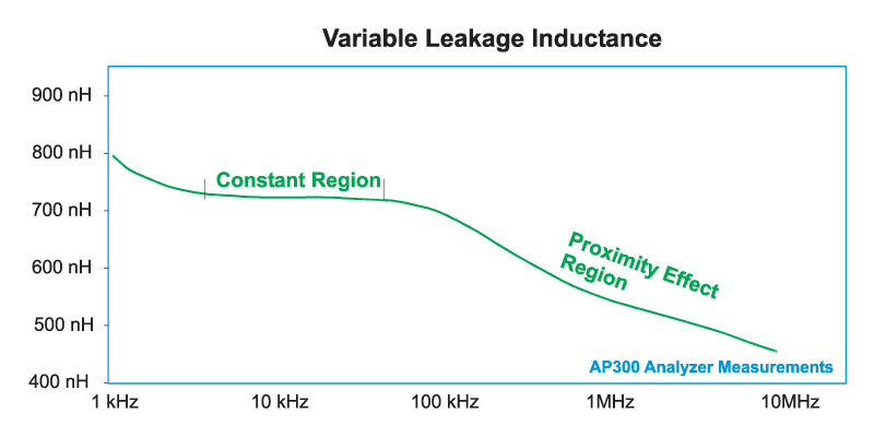
Figure 6: Measured leakage inductance with frequency.
Summary
Every power inductor and power transformer should be properly characterized in terms of its impedance for a full range of frequencies up to at least 10 MHz for typical switching frequencies. This is a tremendous help in resolving problems with your switching waveforms, EMI, snubber design, and magnetics performance. It is also invaluable in showing problems with manufacturing errors and poor workmanship.
Whether you are designing or using magnetics at 1 W or 1 MW, the importance of making these measurements cannot be overstated. Do not overlook or skip this crucial part of your design and manufacturing process. It will always save you time and money during your product development.
References
Additional Reading
- Join our LinkedIn group titled “Power Supply Design Center”. Noncommercial site with over 7000 helpful members with lots of theoretical and practical experience.
- For power supply hands-on training, please sign up for our workshops.
- AP300 Frequency Response Analyzer Manual, www.apinstruments.com.
- “Measuring Frequency Response”, Ray Ridley
- “Core Loss Modeling and Measurement”, Chris Oliver, Micrometals
- “Modeling Ferrite Core Losses”, Ray Ridley
- “Proximity Loss in Magnetics Windings”, Ray Ridley