


Desiging current transformers for fast sensing on the forward converter.
Introduction
This article continues the series in which Dr. Ridley documents the processes involved in taking a power supply from the initial design to the full-power prototype. At this point in the design, the second layout of the PC board is complete, with several significant changes to the power specifications being implemented. The new power supply layout is an opportunity to redesign magnetics components, starting with the current transformer.
Current Sensing Using a Current Transformer
When working with high power supplies, above 100 W or so, the best way to sense the current in the power stage is usually with a current transformer. This approach has the following advantages over resistive sensing of the current:
1.Sense voltage can be large (>1 V).
2.Dissipation can be arbitrarily low.
3.Galvanic isolation eliminates grounding problems. (very important for bridge current-balancing.)
A current transformer consists of a multi-turn secondary wound on an ungapped core, and a single turn primary which usually consists of just a wire jumper on the board, or a copper strap.
Figure 1 shows the schematic of the forward converter with a current transformer in the high side of the input rail, above the drain of the upper FET. The location of the current transformer is important – it should be placed in a part of the circuit where the common-mode ac voltage is small, and where only the desired current is sensed. If the current transformer in Figure 1 were placed on the return of the input rail, it would also sense the gate drive current pulse in addition to the drain current.
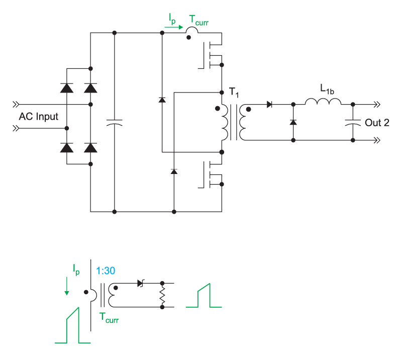
Figure 1: Forward Converter with Current Transformer Placement and Waveforms
The first consideration in selecting a current transformer is the turns ratio. The primary side of the transformer is driven by the current in the power stage, and is set by the load and power stage operating conditions. If you want a given signal size for the control circuit to use, the turns ratio of the current transformer will determine how much voltage drop, and hence how much dissipation, will be seen on the primary. The lower the dissipation that you want, the higher the turns count of the current transformer.
Current Transformer Termination
Proper termination of the current transformer is important. Once the secondary current is found from the primary current and the turns ratio, the value of the terminating resistor is defined to give the desired output voltage. For example, for the forward converter in this article, the peak input current is 4 A at full load, and the desired current sense voltage is 4 V, scaled to work with the UC3825 controller. The loading resistor on the current transformer is therefore equal to the turns count in this case.
As shown in Figure 1, a zener diode is placed in series with the termination resistor. This is the most effective and simplest way to implement a current transformer circuit. When the power current is flowing in the primary, the zener diode conducts, and its presence does not affect the size of the output signal.
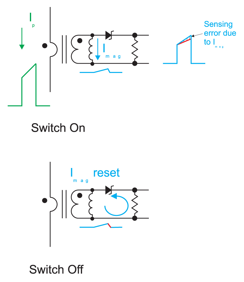
Figure 2: Current Transformer with Magnetizing Inductance
The zener diode is used to provide reset of the magnetizing current of the transformer, as illustrated in Figure 2. In this schematic, the magnetizing inductance is shown on the secondary side of the transformer. When the power circuit is on, voltage is applied across this inductance according to the voltage generated by the load resistor. The magnetizing current increases during this period. This current will subtract from the reflected primary current flowing through the load resistor, and this will affect the accuracy of the current sensing, as shown in the waveform at the output of the current transformer network.
When the switch is turned off, the magnetizing current must continue to flow. It cannot flow in the primary of the current transformer, so it flows up through the loading resistor, and backwards through the zener diode. The zener provides a reset voltage across this inductance, and a 15 V zener will quickly reset the magnetizing inductance back to zero.
You will see many other schemes for resetting a current transformer in application notes. Sometimes a regular signal diode is used in place of the zener. This results in a large reset voltage, limited only by the breakdown of the diode, or a resonant voltage. This large voltage can adversely affect the control circuit in some cases. Other application notes use resistors on the secondary side of the current transformer, but these do not provide a proper reset. The zener solution is the simplest and most effective way to reset the transformer.
Current Transformer Parasitic Elements
It is very important to measure the magnetizing inductance of a current transformer in order to ensure that you are getting the sensing accuracy that you want. It is also important to measure the leakage inductance of the current transformer network, and the winding capacitance. These elements are shown in Figure 3, with the leakage inductance reflected to the primary of the transformer.
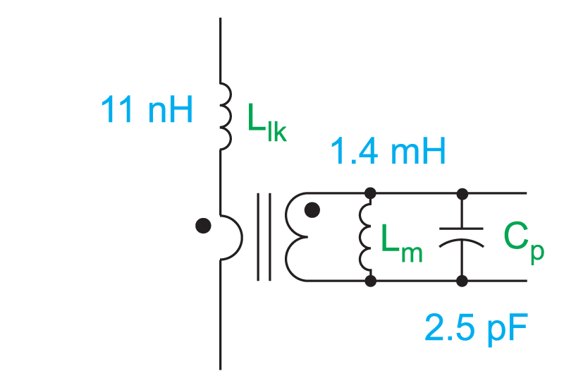
Figure 3: Current Transformer with Leakage Inductance and Winding Capacitance
The leakage inductance of the current transformer network is very important since it will affect the power circuit waveforms if it becomes too large. The leakage is measured by looking at the impedance from the secondary of the transformer, then reflecting the value by the turns ratio squared to the primary side. This leakage value should always be considerably less than the leakage inductance of the main power transformer.
It is interesting to note that the leakage inductance of the current transformer does not determine the bandwidth of the current sensing network. (For normal applications of a transformer, when the leakage impedance reaches the load impedance, that is the bandwidth of the system.) For a current transformer network, it is the capacitance of the windings that determines the bandwidth, so this parameter must also be measured carefully. Since the current sensing network must have very wide bandwidth in order to protect the power circuit properly, the capacitance must be kept as low as possible.
All of the parasitic parameters of the current transformer can be measured as described in the last article in this magazine [1]. On the first pass of the power stage design, an off-the-shelf current transformer was used from Pulse Engineering, as shown in Figure 4. The redesigned transformer, customized for the specific power requirements of this power stage, is also shown.
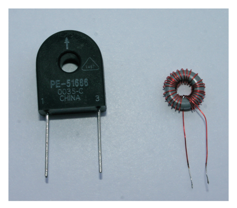
Figure 4: Original Standard Component and Custom Current Transformer
Both current transformers are constructed using a single layer of winding around a ferrite toroid. This provides the lowest-capacitance structure, and is most commonly used for high performance current transformers.
Table 1 – Current Transformer Performance Measurements
|
Pulse Engineering 51886 |
Custom Design |
|
|
Turns Ratio |
50:1 |
30:1 |
| Magnetizing Inductance | 8.8 mH | 1.4 mH |
| Capacitance | 7 pF | 2.5 pF |
| Sensing Error | 1.7% | 5.4% |
| Primary Leakage Inductance | 22 nH* | 11 nH* |
| Bandwidth | 450 MHz | 2.2 GHz |
Table 1 compares the characteristics of the two transformers. The standard part from Pulse Engineering is a good generic part to use in a very wide range of power applications for current up to 20 A, but is quite large for this particular application. The custom design is wound on a much smaller core, and its only drawback is that the magnetizing inductance is lower, and sensing accuracy is less than the standard design.
The capacitance of the custom transformer is very low, 2.5 pF, and the primary side leakage inductance is just 11 nH. This leakage is very low compared to the power transformer leakage inductance of 3.5 µH.
Summary
Designing a custom transformer for your application can optimize the performance for the given space on your board. It is often difficult to find the exact current transformer in a standard part that is small enough for your circuit requirements.
Good current transformer design is not that difficult, consisting of a single layer of wire on a toroidal ferrite core. If the correct termination circuit is used, including a zener reset diode, you should be able to get very good performance out of your current transformer network, and this is the preferred approach for high-power designs.
References
1. “Transformer Impedance Measurements”, http://www.ridleyengineering.com/design-center.html