


[028] Frequency Response Measurement Part 6: Stability Margins
Concepts of gain margin, phase margin, and relative stability.
Introduction
In this article, Dr. Ridley continues the topic of frequency response measurements for switching power supplies. This sixth article discusses the measures of relative stability that can be obtained from a loop gain of a power supply.
Phase Margin of a Control Loop
The previous articles in this series have shown how to make successful frequency response measurements on power supplies, including loop gain. Figure 1 shows the standard loop gain measurement test setup described in the previous articles of this series [1].
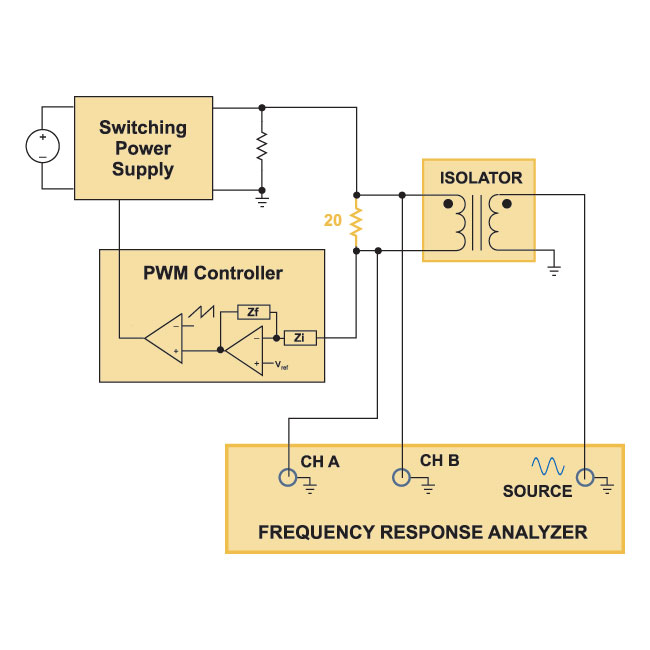
Figure 1: Open Loop Gain measurement with the Loop Electronically Broken.
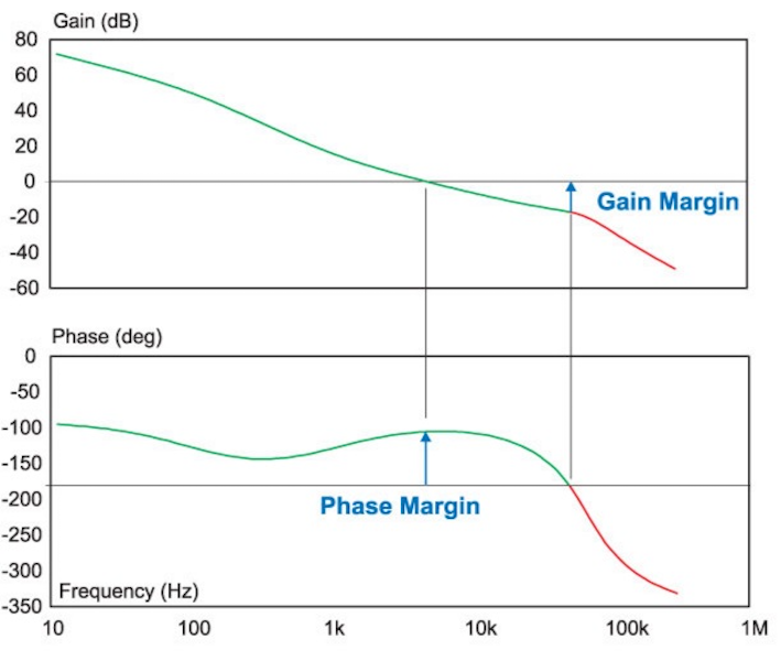
Figure 2 shows a typical measured loop gain with the gain monotonically decreasing with frequency. For this case, definitions of stability are quite clear. At the crossover frequency, where the gain crosses 0 dB, we measure how many degrees the phase is above -180 degrees. This measurement is defined as the phase margin.
(Notice that when you measure the loop with the circuit of Figure 1, the measurement will give the phase margin
directly, without having to measure it from -180 degrees. That is because the measurement test setup includes an extra inversion that was not part of Bode’s original theory for loop gains. )
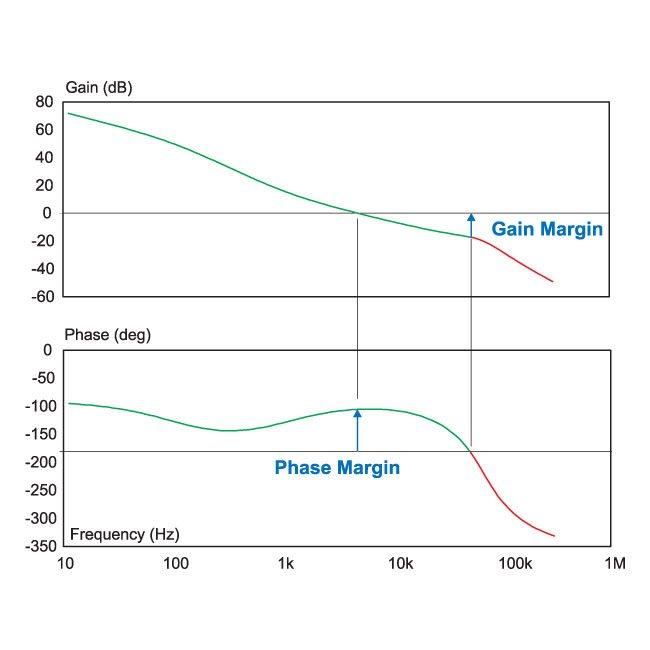
Figure 2: Well-behaved loop gain with monotonic decrease of gain with frequency
The phase margin for the loop gain of Figure 2 is approximately 70 degrees. This amount of phase margin is relatively easy to achieve for a current-mode controlled converter with a conservative crossover frequency.