


Important measurements to make for a power supply design and analysis.
Introduction
In this article, Dr. Ridley continues the topic of frequency response of switching power supplies. Previous articles showed how a frequency response analyzer pulls out a single test frequency from a broad range of noise and signal. This third article shows how the AP300 analyzer can be connected to measure all of the essential transfer functions of a power supply and its components.
Measurement of Passive Components
As mentioned in previous articles in this magazine [1-3], all passive power components should be characterized across the frequency range over which they are required to function. This includes dc measurements for magnetic components, out to 30 MHz, the limit of conducted EMI measurements.
Figure 1 shows the test setup for high impedance measurements (greater than 1 ohm), typically used to characterize magnetics. This is used to measure magnetizing inductances, leakage inductance, resonances, and winding capacitances. Details of such measurements are given in [1-2]. Power magnetics are usually custom-designed, and should be measured to confirm performance. Off-the-shelf parts should also be measured since they are usually inadequately specified by vendors.
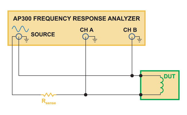
Figure 1: AP300 Setup for high impedance measurements, usually used to characterize magnetics and small capacitances
Figure 2 shows the test setup for low impedance measurements, down to as low as 1 mOhm. This setup is used to characterize power capacitors, and will show capacitor values, resonant frequencies, and equivalent series resistances. All of these quantities can have significant variation depending on the type of capacitor used, temperature, bias point, and batch sample. Most manufacturers do not provide enough accurate data to properly design a power supply, making this an essential measurement for any power capacitor [3].
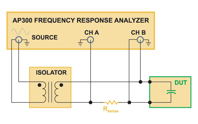
Figure 2: AP300 Setup for low impedance measurements, usually used to characterize power capacitors.
Audiosusceptibility Measurement
In the aerospace industry, it is usually a requirement to measure the input bus to output voltage transfer function, also referred to as audiosusceptibility. This involves the inconvenient process of modulating the input voltage with the frequency response analyzer. More elaborate electronic power sources may have the capability of producing this perturbation, but we usually have to build a circuit to do customized injection, tailored to the specific input voltage and current levels of the converter.
Figure 3 shows a method to inject into the input rail of a power supply. A series-pass FET is used, and its gate is modulated via an isolation transformer. In setting up this test, make sure the FET is rated for the full input voltage, and properly heatsinked for the full input current.
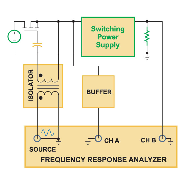
Figure 3: AP300 Setup for input-output conducted noise, or audiosusceptibility, measurement.
Since the input voltage of a power system is typically higher than the allowable range of a frequency response analyzer, it is common to buffer the signal measured at the input voltage. This can be done with a high-voltage differential probe, or using an oscilloscope with a Signal Out feature.
Input Impedance Measurement
The same injection technique as used for audiosusceptibility allows the measurement of input impedance, as shown in Fig. 4. Input impedance is a requirement for most aerospace power systems, and very useful for any large scale systems where power supplies are connected together and system interactions are crucial.
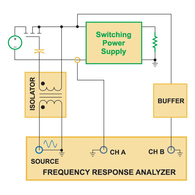
Figure 4: AP300 Setup for input impedance measurement.
For input impedance, the analyzer measures the perturbation of the input voltage and the perturbation of the input current, using a suitable current transducer.
Output Impedance Measurement
Two setups are available for measuring output impedance of a power supply. In the first, shown in Fig. 5, a passive circuit is used via a coupling transformer, and DC blocking capacitor. This test setup can only generate a small current into the output of the power supply due to the limited drive capability of the frequency response analyzer. It is typically useful down to around 10 mOhm output impedance.
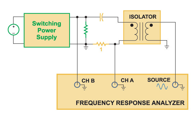
Figure 5: AP300 Setup for output impedance measurement for low power outputs.
For higher current power supply measurement, a higher drive current is needed, and this can be achieved as shown in Fig. 6.
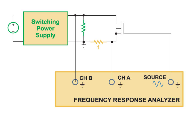
Figure 6: AP300 Setup for output impedance measurement for high power outputs.
Control-to-Output Measurement
Before closing a control loop around a switching power supply, the characteristics of the power stage must be measured. These can be highly variable depending on load, input voltage, and component parasitics, making measurement essential.
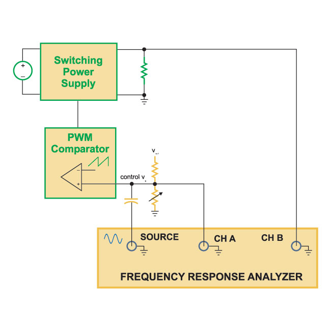
Figure 7: AP300 Setup for output impedance measurement for low power outputs.
It is a common industry practice to set the duty cycle of the PWM controller using a potentiometer which adjusts the control voltage as shown in Fig. 7. The control voltage can then be modulated by ac-coupling to the source of the frequency response analyzer. Care must be taken to keep the power supply operating in its small-signal region at all times, so the proper sized signal must be injected.
Loop Gain Measurement
Once the power stage has been measured, the feedback compensation is designed, and the loop is closed around the system. A very special technique is then used to inject the test signal into the closed loop system, as shown in Fig. 8.
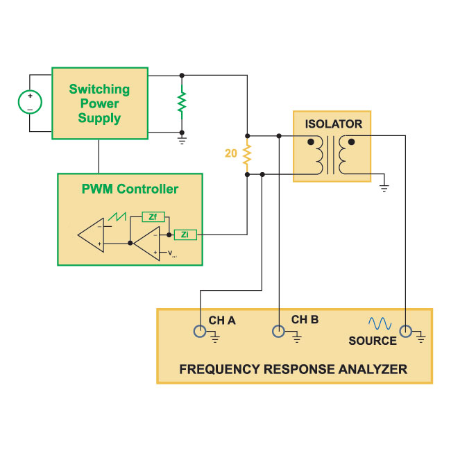
Figure 8: AP300 Setup for loop gain measurement for power supplies.
The test voltage is injected differentially across a 20-ohm resistor via a transformer isolator as shown. With this technique, the loop is kept closed in order to regulate the output voltage, but the voltage impressed across the resistor allows the measurement of the open loop gain. In effect, we are electronically breaking the loop, forcing a difference between the loop input and output signals on either side of the resistor. The next article in this series will discuss this in more detail.
Loop measurement is a very powerful design and diagnostic tool. It allows the compensation design to be verified and adjusted for any nonidealities that may arise in the system. It is also a very sensitive measure of almost all of the components in the power system, and can be used to verify that all of the components are correct.
Summary
This article has provided eight of the most common frequency response test circuits used for characterizing power supplies. All of these tests are useful for ensuring the design of a rugged system, and should be a part of the complete documentation package. For many commercial power supplies, the measurement of audiosusceptibility and input impedance is omitted due to the difficulty of signal injection, but these are also essential for more complex power systems, and a requirement for most aerospace systems.
References
- Join our LinkedIn group titled “Power Supply Design Center”. Noncommercial site with over 7000 helpful members with lots of theoretical and practical experience.
- For power supply hands-on training, please sign up for our workshops.
- “High Frequency Power Transformer Measurement and Modeling”, Power Systems Design Magazine, Design Tips Archive, January/February 2007. http://www.powersystemsdesign.com
- “High Frequency Power Inductor Design”, Power Systems Design Magazine, Design Tips Archive, March 2007. http://www.powersystemsdesign.com
- “Capacitors for Switching Power Supplies”, Power Systems Design Magazine, Design Tips Archive, May 2007. http://www.powersystemsdesign.com