


Control measurements for the Sepic converter.
Introduction
This article shows the measured characteristics of a Sepic converter. Depending on the conditions under which you measure the converter, it can appear either easy to control, or extremely difficult. Make sure you always make an extended range of measurements on your Sepic design if you wish to ensure avoiding the troublesome regions.
Sepic Converter with Wide-Range Input
The Sepic converter is becoming increasingly popular for non-isolated applications. It is a very useful topology in that it can provide either voltage step-up or voltage step-down while preserving the polarity of the input voltage.
The equation for the voltage gain of the converter is shown in Figure 1. At duty cycles less than 0.5, the converter steps down, and at duty cycles greater than 0.5, the converter steps up. (The buck-boost converter has the same gain equation, but it inverts the output voltage.)
Some designers are reluctant to use this converter, however, since it has a reputation for difficult control. Other designers have found that in their application, they have had no difficulty with the control design.
The disparity of opinions about the controllability of the Sepic are aggravated by the difficulty of the analysis for the converter. It is not hard to get Spice simulations of the control bode plots, but analytical expressions are hard to come by. The only known full analysis of the Sepic converter was performed by Dr. Vatché Vorpérian [1], but few engineers are aware of this work.
In this article, we will take a look at the practical measurements on the Sepic converter rather than trying to dissect or simplify the analysis.
Figure 1 shows the schematic of the Sepic converter with component values. The capacitors are multilayer ceramics with very low ESR, and the inductors used were off-the-shelf parts. This is typically how most of these converters are designed, and the available standard inductors are quite good for lower power applications (<50 W). Above 50 W, many designers will switch to custom-designed inductors.
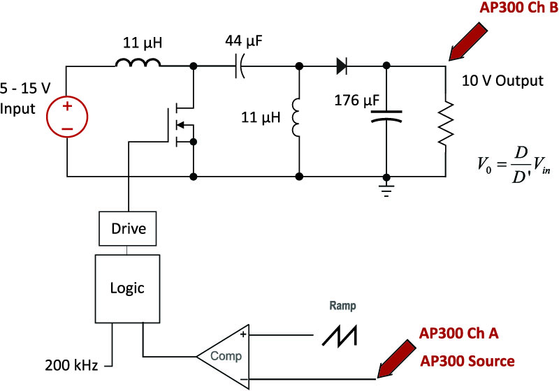
Figure 1: Sepic Converter Circuit for Control-to-Output Measurements with the AP300 Analyzer
The AP300 analyzer [2,3] was used to inject a test signal into the converter, and measure the gain and phase response from input to output.
Sepic Converter Well-Behaved Transfer Functions
Figure 2 shows the measured transfer function of the Sepic converter with an 8 V input. There is nothing particularly remarkable about the gain and phase curves shown. There is a main converter resonance at about 2.5 kHz, and the phase curve ends up with about 270 degrees phase delay. As Vorpérian showed, there is a low-frequency double pole and a right-hand-plane zero explaining the dominant characteristics in this figure.

Figure 2: Measured and Predicted Control-to-Output Transfer Function for an 8 V Input
There is a second “blip” in the transfer function at around 7 kHz, but this is almost unnoticeable in the lab, and certainly not an indication of any difficulties with the converter. (Most engineers in the lab would probably ignore this perturbation, attributing it to noise in the measurement.) Vorpérian showed that this characteristic is caused by a second double pole, with a pair of complex zeros at almost the exact same location. Depending on the operating conditions of the converter, the damping of the second pole pair and complex zeros will change.

Figure 3: Well-Behaved Transfer Functions for the Sepic Converter
Figure 3 shows the range of input voltages for which the Sepic converter does not present a particularly difficult challenge. The input voltage increases from 8 V to 15 V, and the set of curves do not drastically differ from each other. The dominant double pole shifts with input voltage, as does the location of the RHP zero. However, the curves are quite well-behaved with no abrupt changes.
Sepic Converter Poorly-Behaved Transfer Functions
The situation changes as the input line is lowered. Figure 4 shows a family of poorly-behaved transfer functions for the same converter. At a 6-V input, the blue curve shows a more noticeable perturbation at the second resonance. The blue phase curve has a bump at this frequency, but it is still not something indicating impending trouble.
The green curves show the response for a 5.15 V input. Now the gain has a very pronounced dip in it due to the damping of the complex zeros changing. Clearly something more pronounced than just a noisy measurement is causing this.
The final curve, shown in yellow, is much more alarming. There is a very sharp dip in the gain, and the phase flips by 360 degrees. This can easily be missed if you have a low-resolution analyzer since the sharp drop in phase can be misinterpreted and phase-wrapped so that it cannot be seen. However, the 360 degree change is quite real, and this is caused by the complex zeros of the transfer function moving into the right-hand plane.

Figure 4: Poorly-Behaved Transfer Functions for the Sepic Converter
An alarming feature of this converter is that the transition from normal zeros to right-hand-plane zeros is a function of the parasitic elements of the power supply. Normally, increased resistances due to temperature rise serve to damp the characteristics in a power supply, making the converter easier to control. This is not the case with the RHP zeros of the Sepic converter. As the temperature rises, increasing the resistances of the power FET and the inductors, the 360 degree phase flip occurs at higher voltages.
Also, the abrupt change in phase can be eliminated in some cases by blowing on the heatsink of the FET! This is not an acceptable situation for many designers, causing them to avoid the converter altogether. Although Vorpérian has presented analysis in full for the converter, the uncertainty of the response with changing parasitics is disconcerting.
The full set of transfer functions for the Sepic is shown in Figure 5. This indicates the control challenge that the Sepic can present to the designer.

Figure 5: Poorly-Behaved Transfer Functions for the Sepic Converter
Notice that all of the transfer functions of Figure 5 are with CCM operation. An even wider range of results can be expected if the converter is taken into discontinuous mode (DCM).
Summary
The Sepic converter can exhibit very difficult transfer functions when operating at low-line and full load. While this should not be a reason to dismiss the Sepic converter entirely, it is important that designers of this converter are aware that there may be impending trouble in the designs, and they should make sure they have thoroughly tested the converter with a frequency response analyzer, and tested well beyond the intended operating range to ensure design margin.
Testing should also be done at high temperatures since the unpleasant characteristics of the converter are worse as parasitic resistances increase. If you do not see any sharp dip in the magnitude response of the Sepic, you are probably well away from the converter’s region of trouble, and you can be sure that it will behave well for the lifetime of the product.
The next article in this series will examine the effect of current-mode control and coupled-inductor design on these characteristics.
References
- Join our LinkedIn group titled “Power Supply Design Center”. Noncommercial site with over 7000 helpful members with lots of theoretical and practical experience.
- For power supply hands-on training, please sign up for our workshops.
- “Sepic Converter Analysis Notes”, Dr. Vatché Vorpérian
- AP300 Application Notes and Videos, http://www.ridleyengineering.com/analyzer.html