


Control measurements for the Sepic converter with coupled inductors.
Introduction
This article shows the measured characteristics of coupled-inductor Sepic converters and compares them with a separate inductor Sepic. The coupled-inductor Sepic has less diverse transfer functions, but it is still a challenge to control over a wide range. Publications in the past have discussed the coupled-inductor topic, but rarely are the transfer functions shown.
Sepic Converter with Wide-Range Input
The only known full analysis of the Sepic converter was performed by Dr. Vatché Vorpérian [1], but few engineers are aware of this work. It is difficult to follow since the Sepic can have very diverse transfer function characteristics.
In the last article of this series, the separate inductor Sepic was examined. It was shown that very complex characteristics were measured, especially at low input line. They could even change with temperature of the power devices and measurement is essential. In this article, we move on to the coupled-inductor Sepic to see how coupling affects the control performance.
Figure 1 shows the schematic of the Sepic converter with component values. The inductors are wound on a single core with a magnetizing inductance of 11 µH. This is the same as the value of each of the two inductors used in the last article.
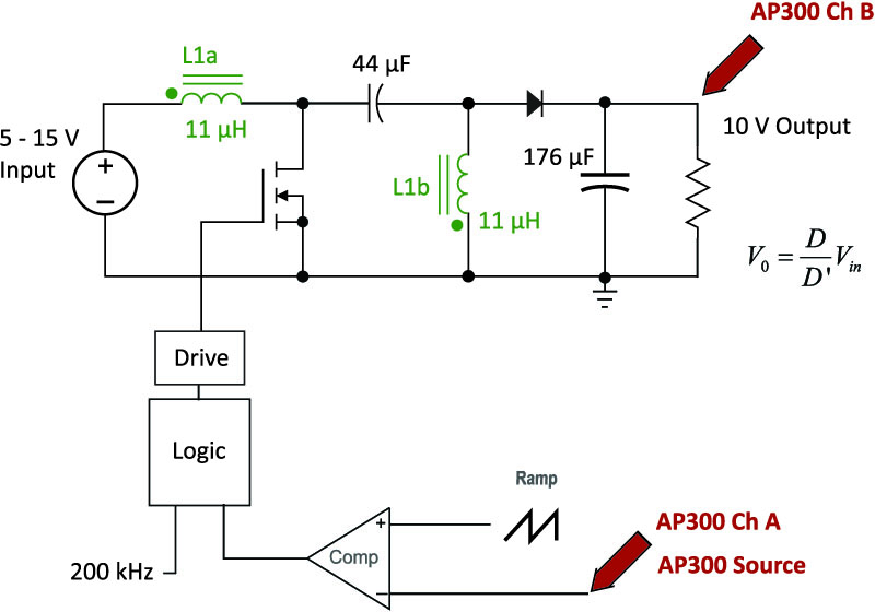
Figure 1: Coupled-Inductor Sepic Converter Circuit
The inductor used for the design used an RM6 core, with two windings wound bifilar with each other to minimize leakage inductance. Figure 2 shows the equivalent circuit model of the coupled inductor. With the bifilar winding, the leakage inductance was measured on an AP300 to be 0.15 µH.
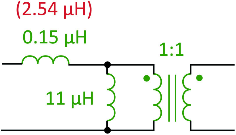
Figure 2: Equivalent Circuit Model of the Coupled Inductor with Tight and Loose and Coupling
Figure 3 shows input ripple currents for the separate-inductor Sepic and for the tightly-coupled Sepic. With the separate inductors, the current is shown in yellow, and the classic linear-ripple slope of PWM converters is apparent.
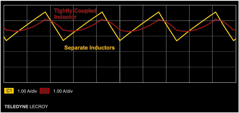
Figure 3: Input Ripple Currents for the Sepic with Separate and Tightly-Coupled Inductors
With the inductors combined onto a single core, the ripple current was reduced, as indicated in the red waveforms. This is a result of coupled-inductor ripple steering, an advanced topic beyond the scope of this article. With the proper value of leakage, it is possible to reduce the input ripple current to almost zero.
Sepic Converter Transfer Functions
The AP300 analyzer [2,3] was used to inject a test signal into the converter, and measure the gain and phase response from input to output. In Figure 4, the range of transfer functions of the separate inductor Sepic is shown. As was discussed in the last article, at low line there was an abrupt flip in the phase response. The converter is very difficult to control in that region unless the bandwidth is significantly compromised.
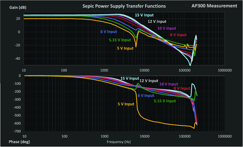
Figure 4: Range of Transfer Functions for the Separate-Inductor Sepic
Figure 5 show the range of transfer functions for the tightly-coupled inductor design. The low-line response is much less severe. Past articles have referred to the better behavior as “benign”, but the converter still has quite an extreme range of gain and phase. Careful attention must be paid to the design of the control loop due to a moving resonant frequency and a moving RHP zero.
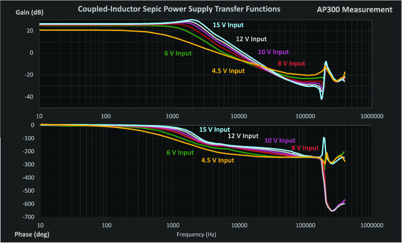
Figure 5: Range of Transfer Functions for the Tightly-Coupled Inductor Sepic
A second inductor was wound with loose coupling between the primary and the secondary windings. The leakage inductance was increased to 2.54 µH with this design. Figure 6 shows the input ripple currents with both a tightly-wound inductor and a loosely-wound inductor. The inductor with poor coupling exhibited a lower ripple current than the tightly-wound inductor.
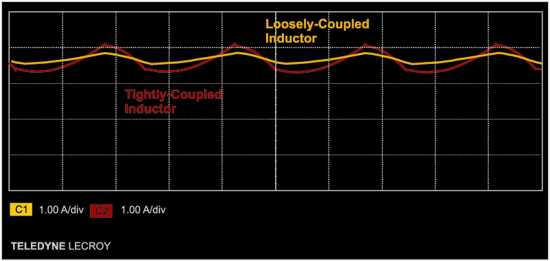
Figure 6: Input Ripple Currents for the Sepic with Loosely- and Tightly-Coupled Inductors
The transfer function at low line for the two design cases is shown in Figure 7. It can be seen that there is little difference between the two designs in terms of the response. This observation holds for the full range of operation of the two designs, and the degree of coupling did not substantially affect the measurements.
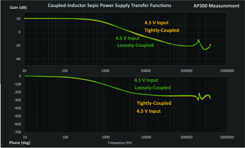
Figure 7: Low-Line Transfer Functions for the Sepic with Loosely- and Tightly-Coupled Inductors
Sepic Converter Efficiency
In winding the inductors for this converter design, interesting effects were seen on the efficiency of the converter. The biggest increase in efficiency came with changing from off-the-shelf inductors to a custom single-core design when the inductors were coupled. This was mostly due to a diferent inductor structure, changing to a gapped ferrite from a powder material. Remember that off-the-shelf inductors are usually optimized for cost, and you can often do better if you have more space or a different profile to work with. Being able to try your own custom magnetics is key to success.
In moving from a tightly-coupled design to a loosely-coupled design, the efficiency dropped. This is due to the fact that an RM6 core was used, and the arrangement of windings had to be significantly changed to get a high leakage. Different results can be obtained if you use a toroid where the single-layer winding structure can be maintained in both cases.
Summary
The coupled-inductor Sepic converter has improved transfer functions over the non-coupled design. This article has shown the experimental measurements of the transfer functions in order to quantify the extent of the changes.
In either case, it is important to characterize the transfer function properly for the Sepic converter by making measurements over the whole range. The analysis is complex, and not always accurate due to the variability of parasitic elements.
References
- Join our LinkedIn group titled “Power Supply Design Center”. Noncommercial site with over 7000 helpful members with lots of theoretical and practical experience.
- For power supply hands-on training, please sign up for our workshops.
- “A New Small-signal Model for Current-Mode Control”, Raymond B. Ridley,1990 PhD dissertation, free download is available.
- Measuring high-performance loops, https://www.youtube.com/watch?v=CbjtGZtaUaQ