


Measuring the Sepic converter control transfer function with current-mode control.
Introduction
This article shows the measured characteristics of Sepic converter using current-mode control, either with a coupled inductor or separate inductors. It is shown how the characteristics are much improved with current-mode, but the complex RHP zeros are still present under low line conditions.
Sepic Converter with Voltage-Mode Control
In the last article of this series, the coupled-inductor Sepic was examined. It was shown that coupling the two inductors on the same core leads to much better behaved transfer functions when voltage-mode control was used. The coupling of the inductors, whether loosely or with very little leakage, eliminated the troublesome second-resonance characteristics and complex RHP zeros.
Figure 1 shows the schematic of the Sepic converter with voltage-mode control.
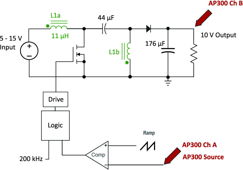
Figure 1: Voltage-Mode Coupled-Inductor Sepic Converter Circuit
The AP300 analyzer [2,3] was used to inject a test signal into the converter, and measure the gain and phase response from input to output. In Figure 2, the range of transfer functions for the coupled-inductor Sepic is shown.
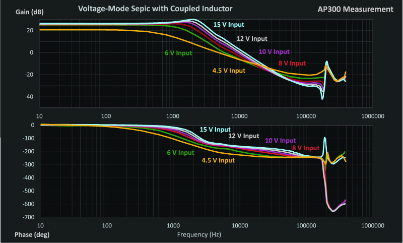
Figure 2: Voltage-mode Transfer Functions with Coupled Inductors
With coupled inductors, there is no indication of a second resonance or the complex RHP zeros characteristic of the Sepic operating at low line. However, there is a still a moving first resonance and a moving real RHP zero. This is very similar to the boost and flyback converters operating in CCM.
Sepic Converter with Current-Mode Control
Figure 3 shows the Sepic schematic with current-mode control. A current transformer in series with the power FET is used to generate a signal proportional to the current, and this is fed into the PWM comparator along with a compensating ramp. The compensating ramp is needed to prevent subharmonic oscillations, as discussed in [7].
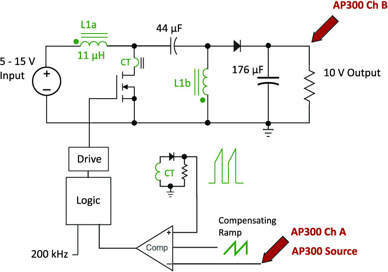
Figure 3: Current-Mode Coupled-Inductor Sepic Converter Circuit
The transfer function from control to output of the converter was measured with an AP300 with the current loop closed. The results of these measurements are shown in Fig 4.
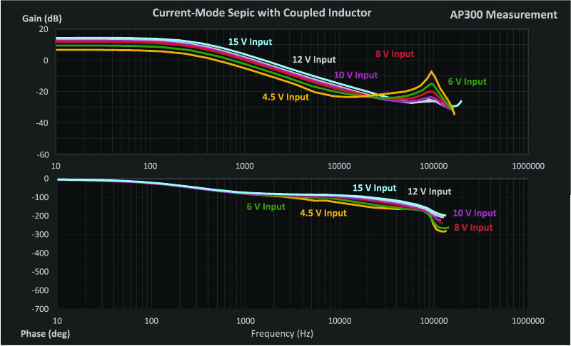
Figure 4: Current-Mode Transfer Functions for Coupled-Inductor Sepic
Comparing the measured responses for current-mode control in Fig 4, and voltage-mode control in Fig. 2, the beneficial effects of current mode can clearly be seen. The moving double pole at 2 kHz is eliminated with current-mode control, and replaced with a single dominant pole at a few hundred Hz.
When large duty cycles occur at low line (gold curve), the peaking of an additional pair of double poles at half the switching frequency is apparent. This is a common characteristic of all converters with current-mode control [7].
The single real RHP zero of the converter is retained with current-mode, and its location is unchanged from the voltage-mode converter. This zero is apparent in the lowest line measurement on the converter.
Current-Mode Control with Separate Inductors
As a final test, the Sepic converter with two separate inductors was run with current-mode control. This was done to verify that coupling the inductors is a crucial step to making this converter stable over a wide range, even if you are using current-mode. The results of the measurements are shown in Fig. 5.
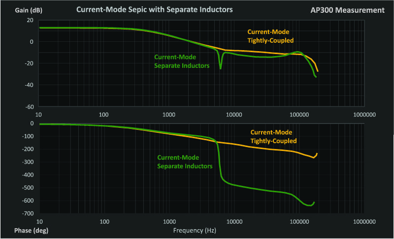
Figure 5: Current-Mode Transfer Function with Separate Inductors
In this figure, the separate inductor measurements are shown in green. The measurements were made at low line, and the second resonance and RHP zeros are apparent. Current-mode control does nothing to change the second resonance characteristics.
The vast improvement with coupled inductors is shown by the gold curve in Fig. 5.
Summary
Current-mode control has a strong beneficial effect on the control characteristics of a Sepic converter. The first filter moving resonance of voltage-mode control is transformed into a dominant single pole. As with all current-mode converters, an additional pair of double poles at half the switching frequency need to be damped with a compensating ramp to avoid subharmonic oscillations.
Even when using current-mode control, it is recommended that the inductors of the converter be wound on the same core to eliminate the second resonance characteristics. The choice of tight or loose coupling can be determined by the desired effect on the inductor ripple currents without worrying about the transfer functions.
If you are contemplating digital control of the Sepic converter, it is an essential step to first couple the inductors, then apply current-mode before implementing digital compensation. The nasty transfer functions of the voltage-mode control with separate inductors cannot be solved with digital algorithms, however complex they may be.
Finally, measurements are essential on these converters. Do not neglect this important step. There are still variable characteristics in current-mode which must be verified on the practical hardware.
References
“Sepic Converter Analysis Notes”, Dr. Vatché Vorpérian, http://www.ridleyengineering.com/design-center.html
AP300 Application Notes and Videos, http://www.ridleyengineering.com/analyzer.html
Measuring high-performance loops, https://www.youtube.com/watch?v=CbjtGZtaUaQ
Join our LinkedIn group titled “Power Supply Design Center”. Noncommercial site with over 7000 helpful members with lots of theoretical and practical experience.
See our videos on loop testing and power supply design at http://www.youtube.com/channel/UC4fShOOg9sg_SIaLAeVq19Q
For power supply hands-on training, please sign up for our workshops at http://www.ridleyengineering.com/workshops.html
Current-mode control book, free for download at http://www.ridleyengineering.com/books.html