


The main switch current of a converter should always be measured to ensure that the converter is operating properly.
Introduction
In an article in June 2007, I wrote about the failure mechanisms of switching power supplies [1]. Almost always, at the heart of the failure, is the power FET. While it is not always the root cause of the failure, it rarely survives, and the failure can be quite dramatic.
Most designers are careful to look at the voltage waveforms on the FET, and this is mentioned as a source of failure of a power supply in [1]. However, many power supplies that I see have no record of current measurement, and this means that engineers often miss impending problems in their designs. The current is not always convenient or easy to measure, but you should always make the effort to look at it. This article gives some tips on making current measurements.
Current Sensing for an Offline Flyback Converter
Figure 1 shows a typical offline flyback converter with an integrated controller. On the primary side, an RCD snubber is used to clamp the voltage peak waveform on the power FET. Application notes often show this waveform under all different conditions, including overcurrent and shutdown mode.
The RCD snubber provides a very effective clamp, and even in cases where there is severe overcurrent in the switch, the effect will not be shown in the voltage across the FET. It is crucial to look at the current in the FET directly to make sure the power supply design is rugged under all conditions.
There is no direct current measurement point available in this schematic. Current sensing is done internally in the power supply controller. In order to measure the current, the circuit traces must be broken at either point A, B, or C. (Conventional lab techniques use a current probe at one of these points, but these are often too large and their inclusion in the circuit can affect the waveforms. In some cases, this can even cause failure of the power supply. )
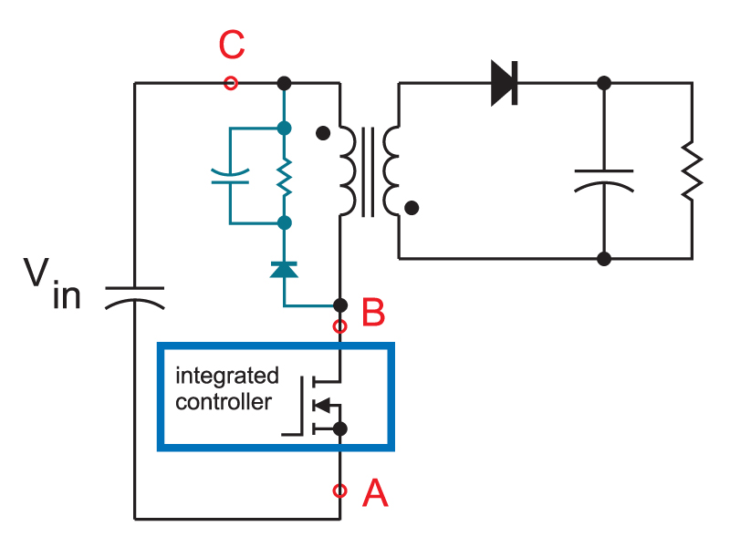
Figure 1: Flyback converter with integrated controller. No current measurement point is immediately available.
If you don’t have a suitably small current probe, you can insert sensing elements in the circuit to accurately measure the current. Figure 2 shows a current sense resistor at point A in the circuit, connected to the source of the FET. If your power supply design does not already have this resistor in the schematic, this is NOT a recommended approach. Integrated controllers can be adversely affected by the inclusion of a sense resistor since the grounding of the controller is changed.
For a discrete controller and FET design, the sense resistor can be used in the source, but bear in mind that the sensed current includes the gate drive current, and this can be substantial for large die FETs. With this setup, the scope ground clip is connected to the negative input rail, and this can present safety concerns for offline converters. It should be done with extreme care. I always recommend isolating the power supply with a line-frequency transformer, and establishing a ground point on the negative rail to make this measurement.
The drain of the FET, point B, is also not a recommended point for measurement. This node of the circuit has the largest voltage excursions, and this will affect the accuracy of current sense resistors, current transformers, and current probes.
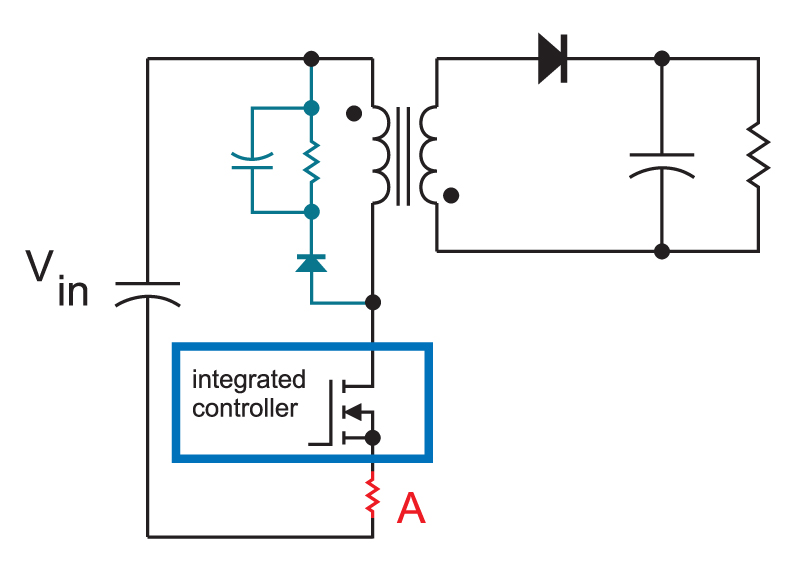
Figure 2: Flyback converter with current sense resistor.
Figure 3 shows a current sense resistor connected to the positive rail of the power supply. This point does not have any high-frequency excursions, and if you isolate the power supply with a transformer, you can put the ground of the scope on the positive rail, and measure the inverted current signal across the resistor. This is a good and reliable method of measuring the drain current, but it has the disadvantage that the signal is very small, and you cannot simultaneously measure the voltage on the drain of the FET.
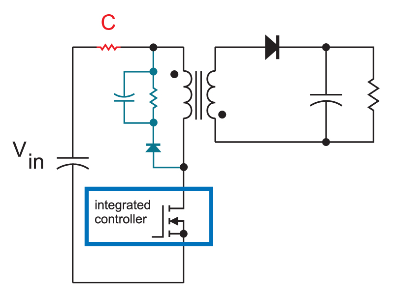
Figure 3: Flyback converter with a current sense resistor from the voltage rail
The current sense resistor method can work well, and certainly is noninvasive in the circuit with a small sized resistor. For low currents, this is a valid approach. Another way to measure the current is with a current-transformer network, as shown in Figure 4. This circuit can provide measurement of small or large currents, and will also provide a larger voltage signal. The current transformer can be a standard component, or a custom made transformer for reduced size. It is important to keep the loop of wire through the current transformer as small as possible since the inductance created will increase the voltage stress on the power FET.
If you are using a current sense transformer network like this, it is often a useful step to compare it to a resistor sense method to make sure your current sensing is working properly. Once the waveforms look good, the current transformer offers the advantage of providing a fully isolated signal, allowing you to look at the current waveform at the same time as establishing a ground on the negative rail of the input converter.
Unlike an active current probe, the current transformer does not have any delay in the sensing that must be compensated for when assessing quantities such as switching losses in the FET. This current sensing network is also the preferred circuit for sensing the signals to be used for feedback in higher power circuit, providing the required accuracy and speed.

Figure 4: Flyback converter with a current transformer from the voltage rail.
Typical Converter Waveforms
The primary switch current for all converters look very similar if they are operating in conventional PWM mode. Figure 5 shows a typical current waveform for a well-behaved converter. There is an initial turn-on spike of current due to recovery of diodes, and stray capacitances. A subsequent ringing is quickly damped out, and the inductor current rise that follows is very linear.
The initial current spike presents problems when using the waveform for current-mode control, but filtering or leading-edge blanking can be used to solve this.
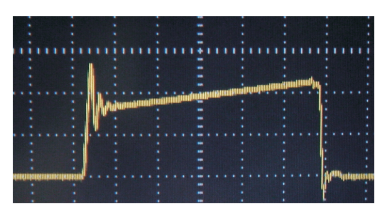
Figure 5: Current waveform for well-behaved converter.
Figure 6 shows the same converter with an output inductor that is saturating abruptly. The slope of the current changes as the core saturates. Even though the power supply is in danger of failing with this condition, the impending problem cannot be seen by just looking at the drain-source voltage waveform on the power FET. The clamp voltage rises slightly, but you cannot see the change in inductance directly. It is essential to monitor the switch current under all conditions to avoid saturation.
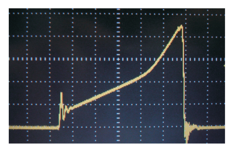
Figure 6: Current waveform with hard saturation with overload
Figure 7 shows another case of magnetics saturation. In this instance, the converter is not overloaded, but the saturation is occurring during startup of the converter. The leading edge blanking period is too long, and the switch current is uncontrolled during startup. This is a relatively common event in converter designs, and it must be avoided to prevent increased failure rates. For high power converters, it is advisable to have a secondary current limit which is active even during the control blanking period in order to prevent severe overcurrent that can lead to failure.
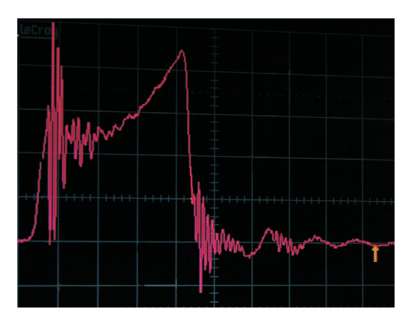
Figure 7: Current waveform with transformer saturation during startup.
Figure 8 shows a converter where the initial current ringing is never properly damped or controlled. The voltage waveforms in the circuit do not reveal this ringing. The ringing in the FET waveform presents serious problems in implementing current-mode control, and prevents accurate current limiting for the circuit.
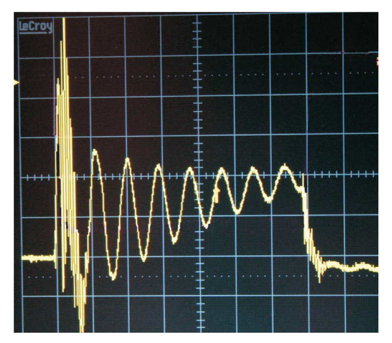
Figure 8: Current waveform with excessive ringing.
Other current waveform anomalies exist in PWM converters, especially bridge or push-pull topologies. It is essential to monitor all the currents to ensure there is no impending imbalance in drives. This can be a very sudden event in full-bridge, half-bridge, or push-pull designs, and the consequences can severely degrade performance, or lead to failure.
Summary
It is not always easy to cut into a circuit to measure the power switch currents, but this is an essential design step to ensure that your converter is rugged under all conditions. Experiment with current-transformer sensing circuits, and you will quickly find this is a very useful approach for monitoring multiple currents in a circuit while maintaining isolation. You should always be careful that current sensing loops are kept as small as possible so as not to introduce increased leakage inductance that change circuit waveforms.
References
- Join our LinkedIn group titled “Power Supply Design Center”. Noncommercial site with over 7000 helpful members with lots of theoretical and practical experience.
- For power supply hands-on training, please sign up for our workshops.
- “Why do Power supplies Fail”, Raymond B. Ridley.