


How to safely test your switching power supplies.
Introduction
In this article, Dr. Ridley shows how to safely test off-line power supplies, without the use of expensive (and sometimes hazardous) high-voltage dc power sources.
Off-Line Power Supply Design and Testing
Off-line power supplies can be dangerous circuits to test and debug, especially at high power levels. Standard off-line designs generate dc input voltages up to 424 VDC after the rectifier – a voltage level that can be hazardous. Proper testing of these power supplies is essential to ensure a reliable product, and this testing must be thorough and safe.
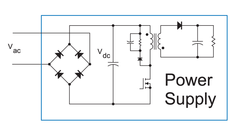
Figure 1: Offline power supply with full-bridge rectifier on input.
Figure 1 shows the typical configuration of an offline power supply, omitting the input filter for simplicity. The ac line is rectified through a full bridge, producing a dc input voltage equal to the peak of the ac input. For a 240 VAC nominal input specification, experienced designers will test their power supplies at up to 300 VAC to ensure proper design margins to cope with real-world variations.
With the circuit configured as shown, there is a problem with testing the power supply. Much of the control circuitry is referenced to the return of the input rail. However, this circuit node is connected to the neutral of the input ac supply for half of the input line cycle, and to the live of the input ac supply for the other half of the line cycle. There is no ground reference for the circuit, making waveforms difficult to measure.
Floating the Oscilloscope
One solution to the problem is to put a “cheater” plug on the oscilloscope, and allow it to “float” at whatever voltage the connection requires. You can certainly do this, albeit very carefully. The oscilloscope will become a part of your system, and will place a complex (high-impedance) load at the connected node of the circuit. Don’t ever connect it to a high-frequency node, such as the drain of the FET of the flyback circuit shown. This will have a drastic effect on circuit waveforms, leading to unreliable measurements or possible failures.
It is acceptable to connect the ground reference of the scope to the negative rail. First, however, you must be aware that the entire body of the scope, and the probe grounds of the other input channels, are then referenced to hazardous voltages. I have done this in the past, but it is always an uncomfortable experience touching the scope carefully and avoiding any metal parts of the instrument.
Differential probes can also be used, but these can be inaccurate when the common-mode voltage is moving by hundreds of volts over a cycle. Failures of semiconductors can be due to events which last for 100 ns or less, and these can be inaccurately observed with ungrounded systems.
Using a High-Voltage DC Lab Supply
Another solution for power supply testing is to use a dc input source. You can purchase lab supplies which have an output voltage range of 500 to 600 VDC. My past experiences have made me wary of this type of supply. There are not many vendors that like to produce such products since the outputs are very dangerous. Also, if you buy a 1 kW supply at 600 V, it can only produce 1.7 A. For low-line testing, this will be inadequate, giving you only 250 W capability at 150 VDC input, the range where many power supply designs will try to get started. Inrush requirements may require that you have a 5 kW dc lab source, just to test a 1 kW power supply design. Such bench supplies are expensive if you can find them.
Past generations of high-voltage dc power supplies have also had some interesting characteristics that can lead to unintentional overvoltage on the input of your test circuit. For example, one particular brand I worked with in the past would surge the input voltage to over 400 V upon activation of the input breaker, regardless of the setting of the output voltage. We learned early in testing to always leave the power supply on, and to connect an additional switch to connect the circuit under test to the output terminals of the supply. The system never felt particularly safe.
There is another drawback to doing DC-only testing. It delays the inevitable fact that you must eventually power the system from an ac supply, and this will produce new events and stresses that can lead to failures. Isolated ac testing will uncover these problems earlier in the design cycle.
Isolating and Re-Grounding The Circuit
My preferred approach to testing is to supply my power circuit with an isolated, variable AC supply. This can be done with a line-frequency transformer and a variac, as shown in Figure 2.
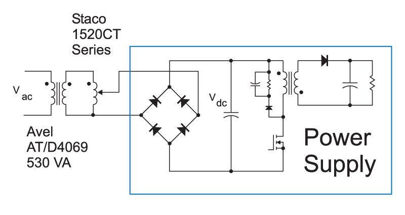
Figure 2: Transformer and Variac used to isolate and control input voltage supply.
The AVEL transformer specified in Figure 1 has dual primaries and secondaries, allowing you to reconfigure connections to provide the desired voltage for testing. The toroidal design provides a low leakage that allows for fast voltage rise time when the input is applied.
This test setup allows you to establish a ground on the power supply being tested. The position of the ground is chosen to suit the measurements that you want to make. It is still inadvisable to ground the circuit at a high-frequency node since this will adversely affect waveforms. However, you do have the choice of grounding either the positive or negative input rail, depending on which quantities you want to measure.
For control and FET voltages for the flyback circuit shown, the ground is connected to the negative rail, as shown in Figure 3. Most testing will be done with the connection, since there are many aspects of the control operation that will need to be verified.
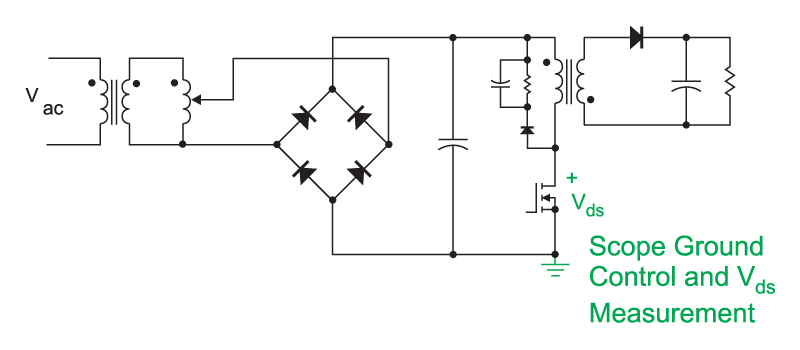
Figure 3: Input negative rail grounded with scope probe for control and Vds measurements
As discussed in [1], sometimes the best way to sense the FET current is with a sense resistor connected to the positive rail of the power supply. In that case, the scope ground is connected to the positive rail, and the voltage measured across the sense resistor, as shown in Figure 4.
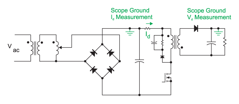
Figure 4: Input positive rail grounded with scope probe for Id current measurement. The secondary can also be grounded for accurate diode voltage measurements.
Depending on how the outputs are referenced to the primary and to the ground, you can also connect a scope probe as shown in Figure 4 to accurately measure the diode voltage stress. Overvoltage on the output diode is a common cause of power supply failures, and it should always be properly measured and documented for all test conditions.
Summary
The safest and most dependable way to design and measure power supplies is to isolate them and establish a proper ground for instrumention. This can be less expensive and safer than using a dc bench supply. Using a floating-ground ac source from the beginning of your experiments minimizes the impact of the eventual connection to the raw ac supply, and speeds up the development process.
Using a grounded scope connected to the appropriate node of the supply under test provides the optimum lab procedure for avoiding shock hazard to users. It also provides the most accurate waveform measurements.
References
- Join our LinkedIn group titled “Power Supply Design Center”. Noncommercial site with over 7000 helpful members with lots of theoretical and practical experience.
- For power supply hands-on training, please sign up for our workshops.