


[054] Hardware Testing and Computer Simulation
Both hardware testing and simulation are essential to understanding power supply designs.
Introduction
In over 30 years of designing power supplies, I have written multiple computer programs to help design, simulate, and understand power supply operation. This has culminated in POWER 4-5-6, the industry's most comprehensive design, simulation and analysis program.
Despite this strong affinity for simulation, when it is time to build or test a real product, my philosophy on designing is very much rooted in hardware. If you are under a high-pressure schedule, you must get to hardware testing as soon as you possibly can.
In this article, a resonant power supply is described, which was my first introduction to power electronics. Simulation was a tremendous assistance in the comprehension of the circuit and in deriving the conditions under which it would work. However, there was no substitute for hardware testing, and the effects seen during this phase of development. While simulation has its place, the main job in power supply development is building the hardware, testing it thoroughly, and doing everything possible during test to ensure ruggedness.
Ferroresonant Power Supply – My Introduction to Power Electronics
Over thirty years ago, I started my first project in power electronics design. Like many of us in this field, it happened quite by accident, and started a lifelong career.
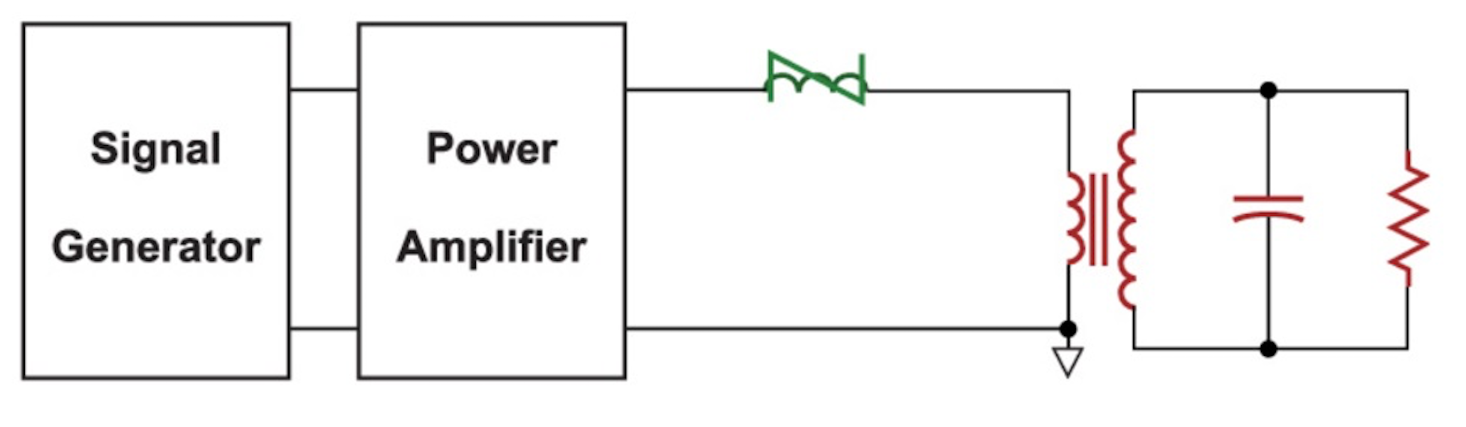
It was a very simple-looking circuit that I was asked to work with as a senior project at Boston University. The input was the rectified ac line, split into positive and negative rails. Two bipolar transistors (this was before the days of power Mosfets) were then operated in a half-bridge configuration to drive a variable-frequency square wave across an LC filter with a transformer.
The circuit is shown in Fig. 1. This is something of a simplification of the real circuit, but it shows the most important elements.
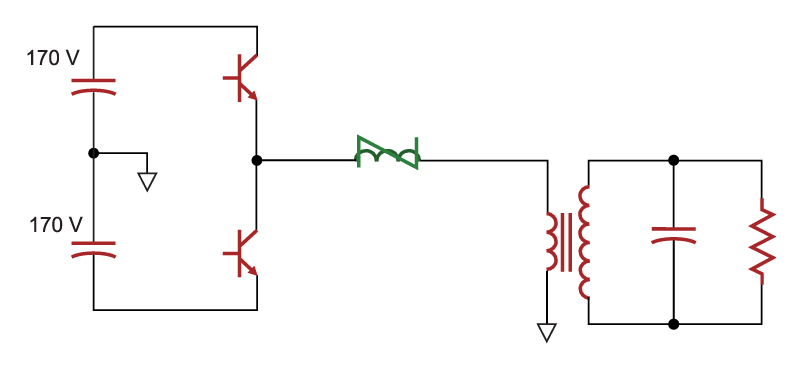
Fig. 1: Half-bridge offline converter driving resonant LC filter with saturable reactor
There were many challenges to this project. First and foremost was the specification.
- Input: 95 to 132 VAC, 60 Hz
- Output: 5000 VAC at 20 kHz.
Furthermore, the output was to be regulated. The application was for a static-eliminator bar inside a copy machine, and the 5000 VAC would produce a corona discharge on the load through which copy paper would pass to have the static charge removed.
This looks like a very daunting task, but at the time I didn’t have enough experience to realize how difficult it should be. Producing a regulated output sinewave is normally something that would be achieved by varying the frequency of the input drive signal, and using the resonant gain characteristics to control the output. This is the more complicated approach.