


A review of Vorperian's PWM switch model which completely changed the task of converter modeling.
Introduction
This article reviews PWM switch modeling, the simplest way to get the small-signal analysis for PWM converters. Dr. Ridley shows how to identify the switching elements, and discusses three forms of the model for different types of analysis.
PWM Converter Modeling
Soon after switching power supplies were implemented in industry in the 60s and 70s, it became apparent that they had unique issues with control that defied normal circuit analysis. This gave rise to state-space averaging, a technique with which the two distinct conditions of the power switch and diode could be combined and analyzed for the first time.
State-space averaging was a powerful analytical tool that enabled development of control systems for many years. However, it was mathematically cumbersome and difficult for newcomers to the field of power electronics to grasp intuitively.
Dr. Vatché Vorpérian developed the PWM switch model in 1986, which replaced the need for state-space averaging and simplified the analysis process. It was a very elegant and intuitive modeling approach, which is easily grasped by new students in the field. Twenty-seven years later, it is still the most accurate and useful way to analyze your circuit.
In this article, we look at the PWM switch elements, and the three forms of the equivalent circuit model which can be used for different types of analysis.
PWM Switch Model
Figure 1 shows the essential switching elements of a power supply. There must always be a controlled switch, and a diode (or second switch) that is on when the controlled switch is off. The junction of the two elements is connected to a common terminal, which will be connected to any inductors in the switching power stage.
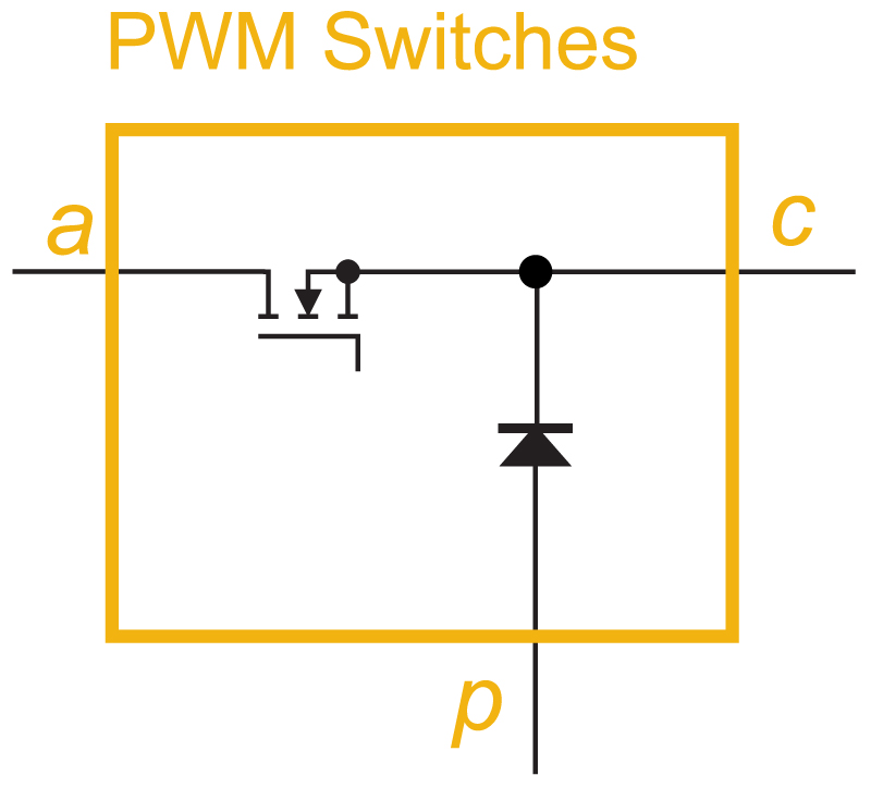
Figure 1: PWM switches needed to create a switching power supply. The diode can also be a synchronous rectifier if desired.
Vorpérian showed that there are three equivalent circuits that can replace the actual switching elements to perform different levels of circuit analysis. The first of these, shown in Figure 2 with red components, enables you to analyze a circuit for nonlinear effects. This equivalent circuit consists of a 1:d transformer. The value of the turns ratio, d, is set by the output of the controller for the power supply, and is a continuously variable function with a value between 0 and 1. Switching is eliminated in this circuit.
This circuit can be used by an analysis program such as Spice to predict waveforms and small-signal analysis, but the nonlinear operation of such an element can cause Spice to have numerical convergence issues under some circumstances.
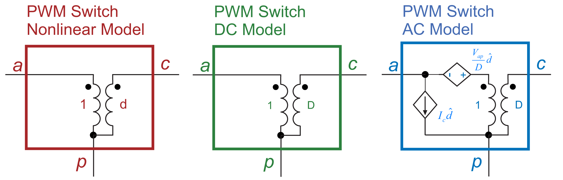
Figure 2: Three different equivalent circuits – the nonlinear switch model, linearized small-signal switch model, and DC switch model.
Linearization is needed if we are to perform manual analysis on a switched-mode power supply to derive symbolic results rather than numerical results. The blue circuit of Figure 2 shows the linearized model which is the one that is most frequently used in the power electronics industry. This equivalent circuit has two additional sources added. Also, a 1:D transformer is added where D is the steady-state duty cycle which defines the operating point of the circuit.
If there is no perturbation of duty cycle and you just want to find the DC gain of a power stage, you can use the green circuit of Figure 2. This retains only the 1:D transformer from the complete AC circuit model shown in blue. This circuit can also be used to find transfer functions that do not involve perturbation of the duty cycle, such as the open-loop output impedance.
PWM Switch Model in Different Converters
The major challenge to implementing the PWM switch model is finding the switch and diode combination arranged appropriately in your particular power circuit. This is trivial for the three fundamental circuits—the buck, boost, and buck-boost. As shown in Figure 3, the switch and diode of these circuits naturally appear next to each other. Replacement of the switching elements with the small-signal equivalent circuit is then straightforward.
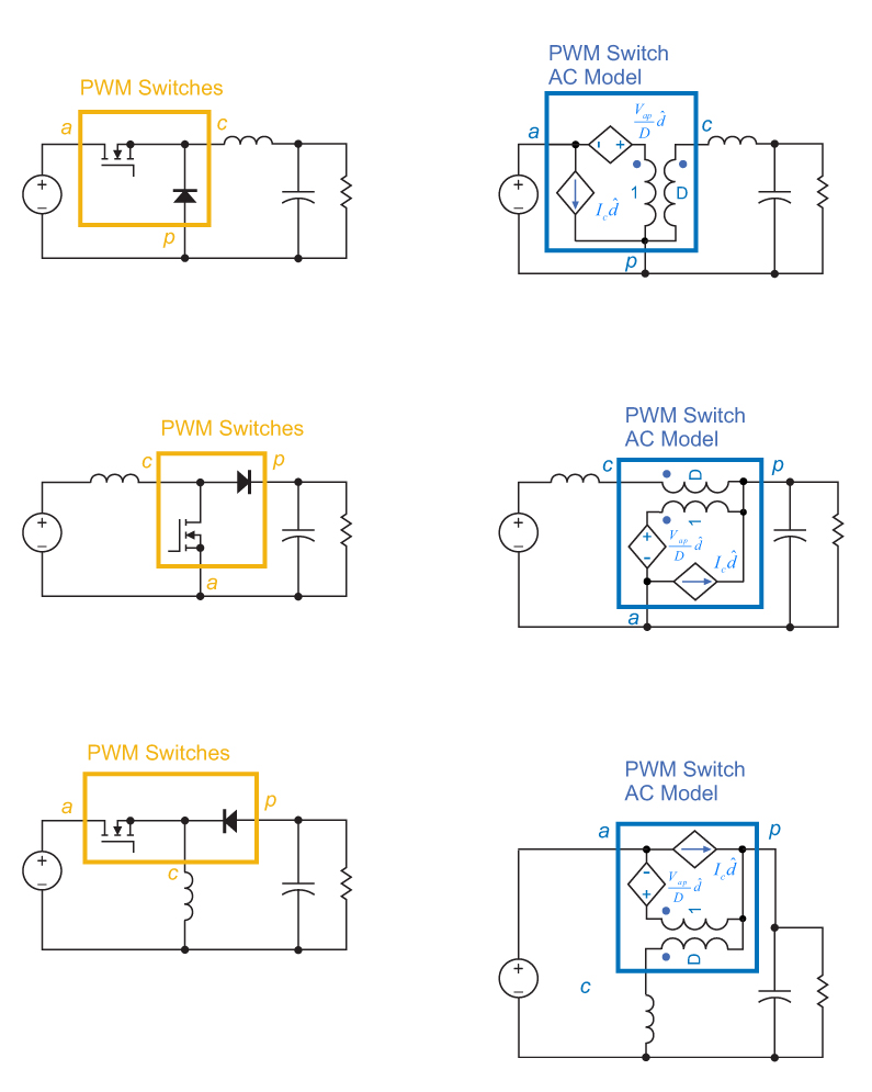
Figure 3: Linearized small-signal switch model inserted into the buck, boost, and buck-boost converters. A single Spice subcircuit suffices for all converters.
Notice that all three of the basic circuits have the same model for the PWM switch subcircuit. However, the converters have very different characteristics—a moving double pole and RHP zeros for the boost and buck-boost, as discussed in [1]. These unusual characteristics are created because of the rotation of the PWM switch, and its insertion between the inductor and capacitor.
When a transformer is used as part of the power stage, the switch and diode can be separated. A little more work is needed on the circuit to identify the PWM switch model. An example of this is shown in Figure 4. For a single-switch forward converter, the switch is on the primary of the transformer, and the diode is on the secondary.
A simple circuit transformation pushes the switch through to the secondary side, where it appears in series with the forward diode. Notice this circuit has a voltage source now connected across an ideal transformer. (We could not implement an ideal transformer in real life, but it is not a problem conceptually, or for Spice to model.) The current in the primary of the ideal transformer is interrupted by the secondary switch.
With the switch moved, the PWM model now appears in its proper form, enclosed by the gold outline. We can now replace the switches with the linearized AC model shown in blue, and circuit analysis can continue. The only difference in this circuit from the buck equivalent model is that there is now a transformer applied across the input voltage. Apart from that, the subcircuit for the PWM switch is unchanged from those of Figure 3.
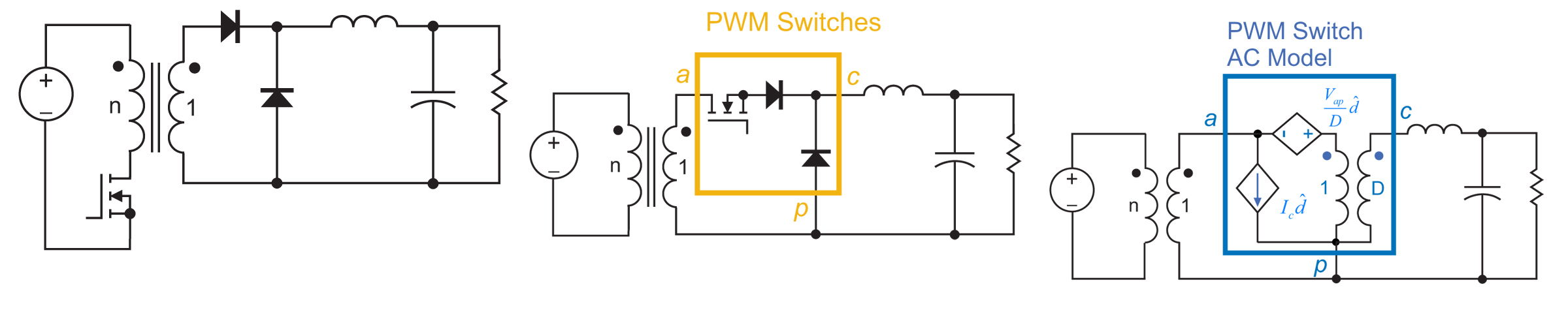
Fig. 4: Rearrangement of the forward converter components reveals the PWM switching components, leading to the small-signal model which includes a transformer.
Figure 5 shows how the flyback converter is rearranged to reveal the PWM switch. First, we add the primary side inductor explicitly to the circuit. This component can then be reflected through to the secondary as shown, with its value reduced by the square of the transformer turns ratio.
Then we can push the switch itself through the transformer. Once we have done this, the PWM switch appears and can then be replaced with the AC small-signal circuit model.
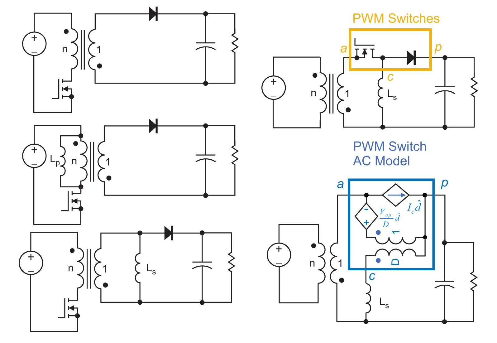
Fig. 5: Rearrangement of the flyback converter puts the inductor on the secondary side.
I have yet to encounter a PWM converter that cannot be quickly rearranged to reveal the PWM switch, and hence be easily amenable to analysis with the PWM switch model. In [2], it was shown how this could be done for the Sepic converter. In the next part of this article, we will tackle some more challenging circuits with tapped inductors.
Summary
There are many new faces coming into the world of power electronics and power supply design. They often have new and useful skills to bring to our field, but have not had time to study the fundamentals of power supply analysis. This is a natural evolution in any field, and new engineers need to search on their own for solutions.
The PWM switch model was discussed in great detail when it was first discovered at conferences and in industry papers, but is now assumed to be background knowledge. I often find that many of our workshop attendees [3] are not aware of the existence of these modeling tools, and it is important to introduce them to the simplicity of PWM switch model application to their circuits.
References
- Join our LinkedIn group titled “Power Supply Design Center”. Noncommercial site with over 7000 helpful members with lots of theoretical and practical experience.
- For power supply hands-on training, please sign up for our workshops.
- Boost and Buck-Boost Converters with Voltage-Mode Control, Articles [17,19],
http://www.ridleyengineering.com/design-center.html - Analyzing the Sepic Converter, Article [02],
http://www.ridleyengineering.com/design-center.html