


Dr. Middlebrook's early paper on current mode indicated a current loop crossover above half the switching frequency, violating Nyquist priciples.
Introduction
In this second part of this series of articles, Dr. Ridley shows how Dr. David Middlebrook approached the analysis of current-mode control, and the consequences of the modeling approach on loop gain predictions.
Current-Mode Control Circuit
Figure 1 shows a buck converter with peak current-mode control. The instantaneous value of the inductor current is added to a compensating ramp, and compared to a control reference, . The inductor current can be sensed in numerous ways, but the important thing is to make sure the sensing is an accurate representation of the real current in the inductor, without any filtering.
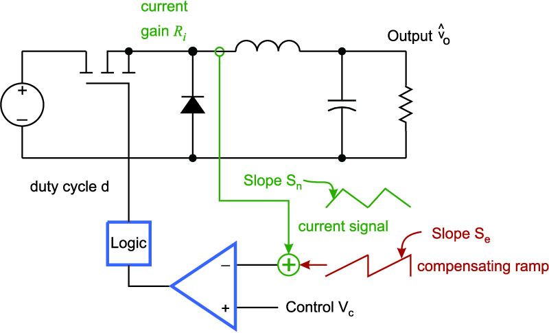
Figure 1: Buck Converter with Current-Mode Control
Figure 2 shows the average model for the buck converter with current-mode control. A feedback loop around the inductor current represents the system. is the gain from inductor current to the voltage signal which is one input to the comparator. All quantities are known in this diagram except for the gain of the modulator, .
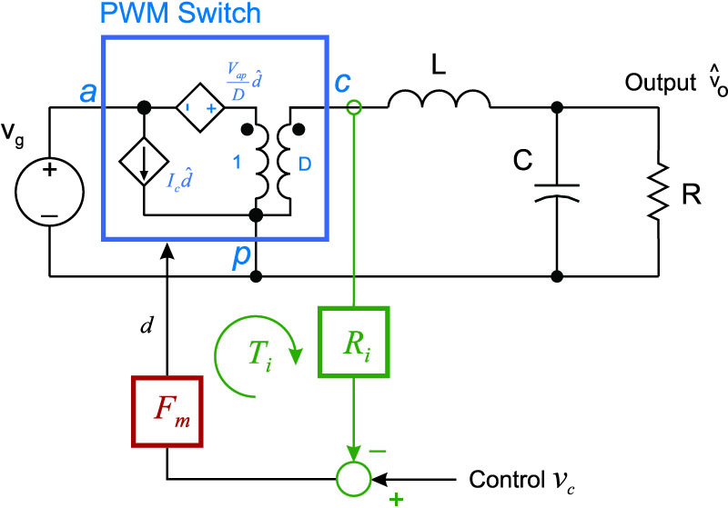
Figure 2: Average Model of the Current-Mode Buck Converter
Early discrepancies arose in determining the gain of this modulator. Different researchers found different solutions to the same problem. Figure 3 summarizes the most common approaches being used in the industry in 1986. The infinite-gain solutions found by Barney Holland and Unitrode are highlighted in Figure 3.
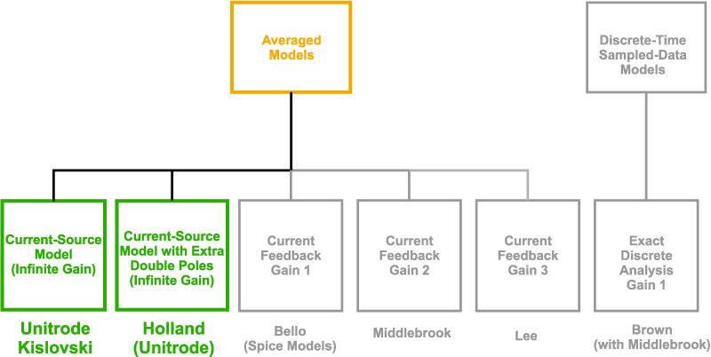
Figure 3: Current-Mode Control Models In 1986: Infinite Gain Models
The infinite gain is what is needed if we assume the inductor has been changed into a current source. In reality, it is not a perfect current source since the peak of the current and the average value of the current are not the same. In this second part of this series, we will examine how Middlebrook looked at the current modulator.
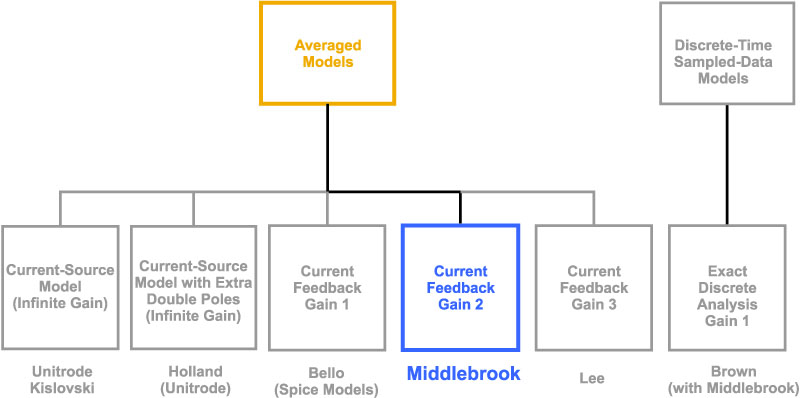
Figure 4: Current-Mode Control Models In 1986: Middlebrook’s Gain Model
Middlebrook’s Modulator Gain Model
In 1986, Middlebrook published his famous paper on current-mode that received a lot of industry and university attention [1]. Current-mode had been popularized several years before this, but Middlebrook brought attention to how the system should be modeled in his own unique and special style.
The first thing he did was to define what is meant by the term “average” current. Middlebrook’s explanation for this was very simple and intuitive: the average current was the value of the inductor current without the ripple. In Figure 5, this is defined as being halfway up the slope of the inductor current which makes good practical sense.
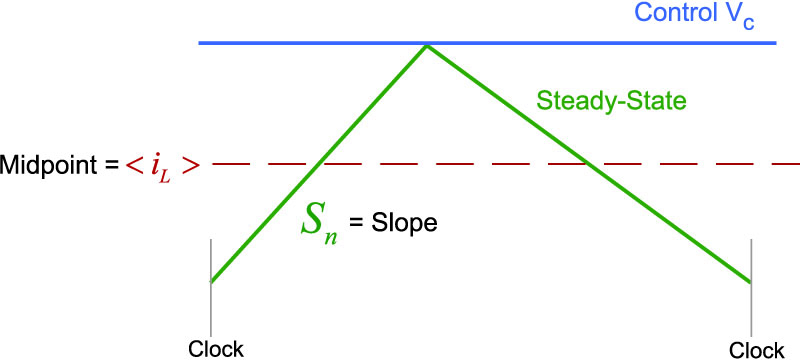
Figure 5: Middlebrook’s Definition of Average Inductor Current
Figure 6 shows the control waveforms with perturbation applied to the system. In order to find the modulator gain, we need to assess how much the duty cycle will change for a given change in the inductor current. The green waveform shows the inductor current in steady-state. At the end of the cycle, the inductor current has returned to exactly the same current level as it was at the beginning of the cycle.
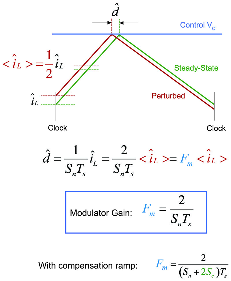
Figure 6: Modulator Gain Derivation Using Middlebrook’s Average Current Definition
Now consider a small perturbation ![]() introduced at the beginning of the clock cycle. When the current hits the control voltage, the perturbation is given by
introduced at the beginning of the clock cycle. When the current hits the control voltage, the perturbation is given by ![]() . The equations of Figure 6 show that the perturbation in duty cycle is just the reciprocal of the slope, multiplied by the initial change in current. However, the perturbation in the average current,
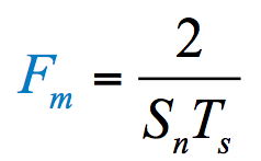
. The equations of Figure 6 show that the perturbation in duty cycle is just the reciprocal of the slope, multiplied by the initial change in current. However, the perturbation in the average current, ![]() , is only half the perturbation in the initial current since the average current defined by Middlebrook is the midpoint of the slope. From this, it follows that the modulator gain for the system is twice as high, given by:
, is only half the perturbation in the initial current since the average current defined by Middlebrook is the midpoint of the slope. From this, it follows that the modulator gain for the system is twice as high, given by:
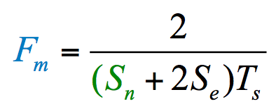
If a compensating ramp is added to the system, the modulator gain term is modified to be:
Middlebrook’s Current Loop Gain and Phase
Given this value of modulator gain, we can now plot the transfer function of the current loop gain that has been created for this system. (For the poles and zeros of this transfer function, please read reference [2]). Figure 7 shows the result for a circuit operating at a duty cycle close to 50%, and without any external compensating ramp added to the system.
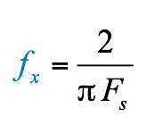
The gain has a low-frequency zero before the resonant frequency, then a double pole given by the resonance of the LC filter of the buck power stage. After the resonance, there is a fixed -20 dB/decade slope. The final crossover frequency for this 50% duty cycle is given by:
In his original paper, Middlebrook described how this current loop crossover translated into a second pole of the control-to-output transfer function at about 2/3 the switching frequency.
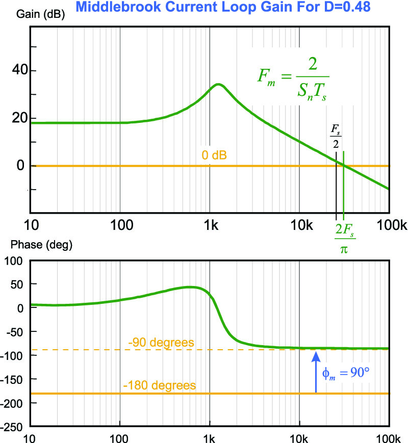
Figure 7: Middlebrook’s Predicted Current Loop Gain and Crossover with 50% Duty Cycle
In the introduction to his paper [1] he makes the following statement:
"….. Therefore, although current programming tends to make the power stage output behave as a current source, the control-to-output voltage transfer function exhibits, in addition to the familiar dominant pole, a second pole at the current loop gain crossover frequency, which may lie anywhere from one-sixth to two-thirds of the switching frequency."
Interestingly, the crossover asymptote of the current-mode loop (without a compensation ramp) is completely independent of the current-sensing gain, or any other circuit values, which seems like an unusual result. The explanation for this is as follows: if we increase the gain of the current sensor we have a higher gain from duty cycle to sensed signal in Figure 2. However, we now have a larger slope on the current, and the modulator gain reduces by the exact same amount. So when we have current mode control, we really don’t have design freedom over the current loop. All we can do is reduce the gain by adding a ramp, but we cannot increase the gain beyond that shown in Figure 7.
There is a second interesting point to be made. The crossover frequency of the current loop predicted by Middlebrook is in excess of half the switching frequency. This would seem to be a violation of the Nyquist criteria which states that you cannot exceed half the switching frequency in a feedback loop. Although the system is nonlinear and time varying, control theorists should immediately be concerned about this predicted outcome.
We will discuss this more later in this series after deriving other possible solutions for the modulator gain for the current-mode system.
Summary
In this article, we have shown how Middlebrook derived the current-loop modulator gain for his assumed definition of average inductor current. The unusual result of predicting a crossover frequency in excess of the Nyquist frequency is caused by the modulator gain that Middlebrook found in his analysis. It should be stressed at this point that there are not any mathematical errors in Middlebrook’s paper, and we will have to look for another explanation for this anomaly.
Next in this series: Dr. Fred Lee’s and NASA’s modulator gains, and the current-source infinite modulator gain derivations.
References
- “Topics in Multiple-Loop Regulators and Current-Mode Programming”, R.D. Middlebrook, IEEE Transactions on Power Electronics PE-2(2) pp.109 – 124, April 1987.
- “A New Small-Signal Model for Current-Mode Control”. Full original version available as a free download at www.ridleyengineering.com/books.html. Updated color version available from Researchgate.
www.researchgate.net/publication/280491161_Current-Mode_Chapter_1 www.researchgate.net/publication/280491229_Current_Mode_Chapter_2
www.researchgate.net/publication/280682067_Current-Mode_Chapter_3
- Power supply design articles www.ridleyengineering.com/design-center.html
- Join our LinkedIn group titled “Power Supply Design Center”. Noncommercial site with over 7000 helpful members with lots of theoretical and practical experience.
- See our videos on power supply design at www.youtube.com/channel/UC4fShOOg9sg_SIaLAeVq19Q
- Learn about current-mode control in our Power Supply Design Workshops www.ridleyengineering.com/workshops.html