


Dr. Lee's early papers indicated a current loop crossover approaching infinity at D=0.5, violating Nyquist priciples by a large margin.
Introduction
In the third part of this series of articles, Dr. Ridley shows how Dr. Fred Lee’s analysis of current-mode control resulted in a high modulator gain, and also shows the consequences of this gain on current-loop predictions.
Current-Mode Control Circuit
Figure 1 shows a buck converter with peak current-mode control. The instantaneous value of the inductor current is added to a compensating ramp, and compared to a control reference. This is the standard implementation of current-mode control, used widely in the power supply industry.
Figure 1: Buck Converter with Current-Mode Control
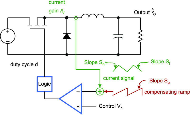
Figure 2 shows the average model for the buck converter with current-mode control. A feedback loop around the inductor current represents the current-mode feedback system. Riis the gain from inductor current to the voltage signal which is one input to the comparator. All quantities are known in this diagram except for the gain of the modulator, Fm In the last part of this series, we found Middlebrook’s expression for the gain of the modulator.
Figure 2: Average Model of the Current-Mode Buck Converter
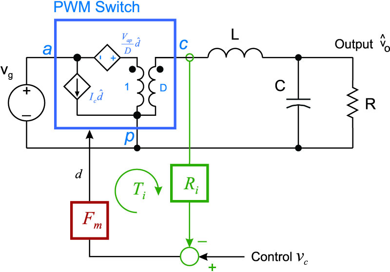
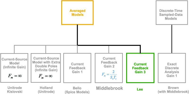
Figure 3 shows the different models for current-mode which existed in 1986. The first two blocks on the left show the infinite gain which is assumed for a current-source model, which is a popular way of looking at current-mode. Middlebrook’s modulator gain is shown in the fourth block from the left. We are now going to find an alternate modulator gain, originally used by Dr. Fred Lee, and later, other researchers such as Dr. Dong Tan.
Figure 3: Current-Mode Control Models In 1986: Lee’s Gain Model
Lee’s Modulator Gain Model
Figure 4 shows the converter inductor current in green, with the perturbed current in red. As we saw in the last part of this series, Middlebrook defined the average current as being halfway up the slope of the inductor current which makes intuitive sense. However, since the current perturbation changes abruptly at the point where it hits the control voltage threshold, this is not the only way to define “average” current.
Figure 4: An Alternative Definition of Average Inductor Current
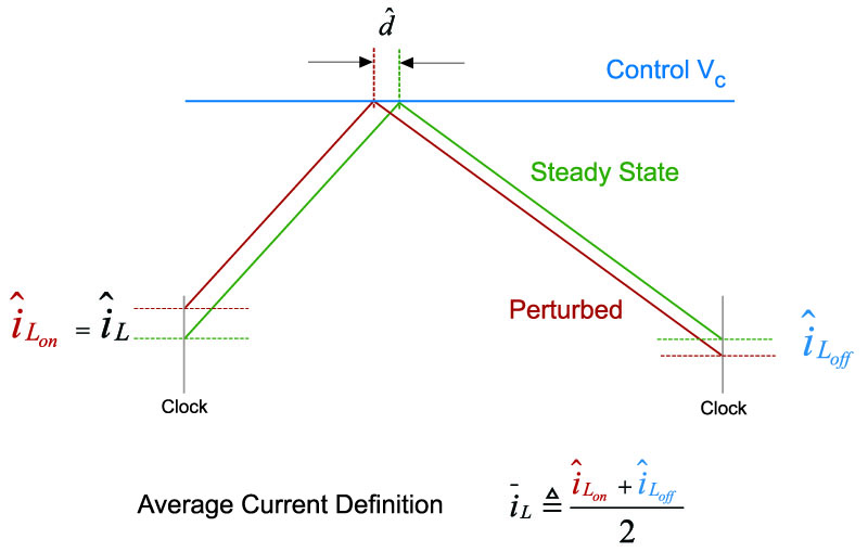
Figure 5 shows the control waveforms with perturbation applied to the system. In order to find the modulator gain, we need to assess how much the duty cycle will change for a given change in the inductor current. The green waveform shows the inductor current in steady-state. At the end of the cycle, the inductor current has returned to exactly the same current level as it was at the beginning of the cycle.
Figure 5: Modulator Gain Derivation Using Lee’s Average Current Definition
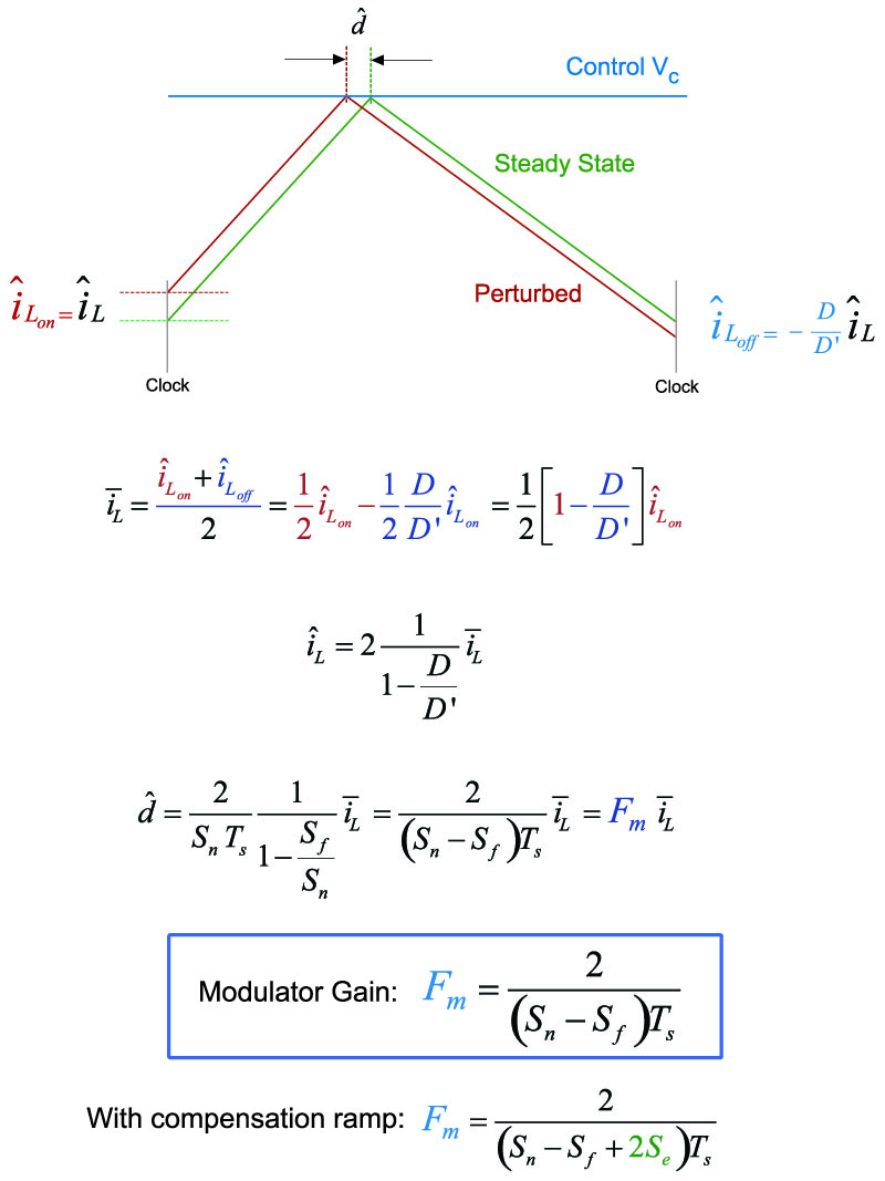
Figure 5 shows how the modulator gain is derived for the alternate average current definition. We can see that the modulator gain is a function of both the on-time and off-time slope magnitudes of the current, as follows.
Notice what happens if these slopes are the same, as would occur at a 50% duty cycle – the gain of the modulator will go to infinity. If a compensating ramp is added to the system, the modulator gain is reduced as shown below:
Lee’s Current Loop Gain and Phase
Given this value of modulator gain, we can now plot the transfer function of the current loop gain that has been created for this system. (For the poles and zeros of this transfer function, please read reference [3]). Figure 6 shows the result for a circuit operating at a duty cycle of 48%, and without any external compensating ramp added to the system.
The gain has a low-frequency zero before the resonant frequency, then a double pole given by the resonance of the LC filter of the buck power stage. After the resonance, there is a fixed -20 dB/decade slope.
Figure 6: Lee’s Predicted Current Loop Gain and Crossover with 48% Duty Cycle
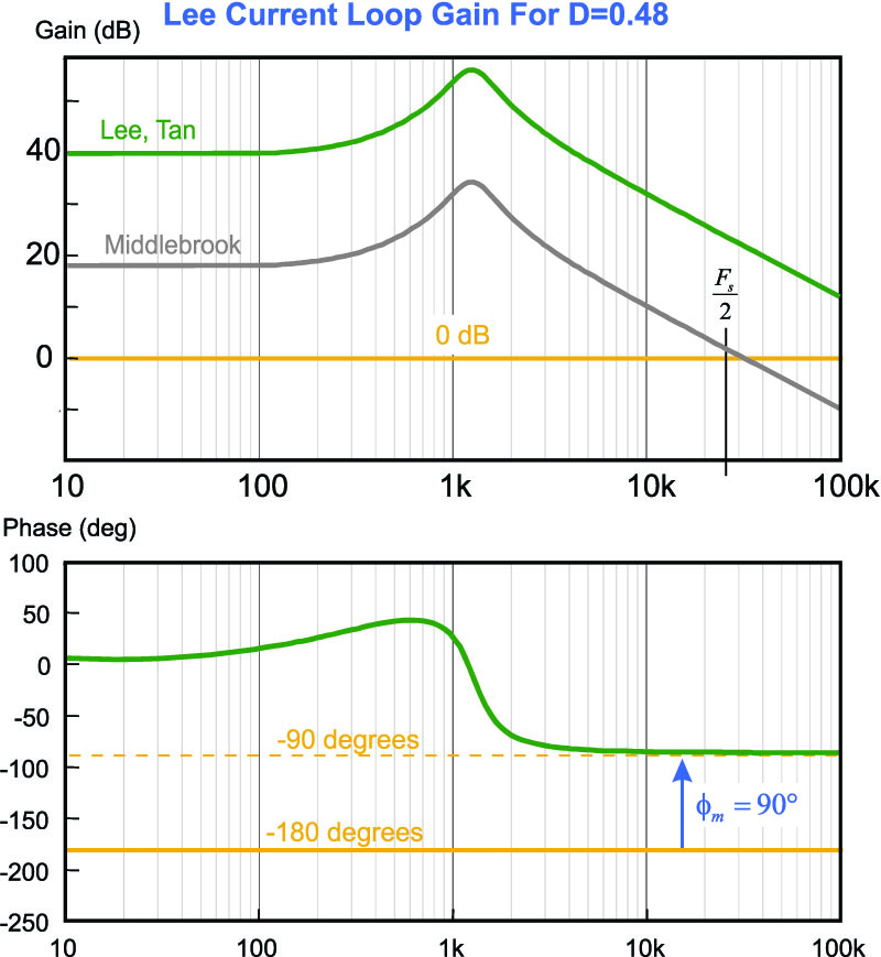
The crossover frequency of the current loop predicted by Lee’s modulator is considerably higher than that by Middlebrook. It is far in excess of half the switching frequency. As observed before with the Middlebrook model, this would seem to be a violation of the Nyquist criteria which states that you cannot exceed half the switching frequency in a feedback loop.
If we operate at a 50% duty cycle, the gain of the modulator is infinite and the resulting crossover is also at infinity.
Summary
In this article, we have shown how a different definition of average current from Middlebrook’s original definition results in a modulator gain which is much larger, and which can go to infinity at a 50% duty cycle. As with Middlebrook’s modulator gain, the crossover of the current loop gain is well in excess of half the switching frequency, an apparent violation of Nyquist criteria.
Next in this series: current-source infinite modulator gain derivations.
References
[1] "A Unified Analysis and Design Procedure for a Standardized Control Module for DC-DC Switching Regulators”, F.C. Lee, Y. Yu, M.F. Mahmoud, "A Unified Analysis and Design Procedure for a Standardized Control Module for DC-DC Switching Regulators," Power Electronics Specialists Conference, 1980 Record, pp.284-301.
[2] “Topics in Multiple-Loop Regulators and Current-Mode Programming”, R.D. Middlebrook, IEEE Transactions on Power Electronics PE-2(2) pp.109 – 124, April 1987.
[3] “A New Small-Signal Model for Current-Mode Control”. Full original version available as a free download at www.ridleyengineering.com/books.html. Updated color version available from Researchgate.
www.researchgate.net/publication/280491161_Current-Mode_Chapter_1 www.researchgate.net/publication/280491229_Current_Mode_Chapter_2
www.researchgate.net/publication/280682067_Current-Mode_Chapter_3
[4] Power supply design articles www.ridleyengineering.com/design-center.html
[5] Join our LinkedIn group titled “Power Supply Design Center”. Noncommercial site with over 7000 helpful members with lots of theoretical and practical experience.
[6] See our videos on power supply design at www.youtube.com/channel/UC4fShOOg9sg_SIaLAeVq19Q
[7] Learn about current-mode control in our Power Supply Design Workshops www.ridleyengineering.com/workshops.html