The correct modulator gain is confirmed by experiment. Different analysis results are completely resolved when choosing the right modulator gain.
Introduction 2
In the last part of this series, Dr. Ridley shows that only one of the modulator gains found in the literature can be confirmed with measurements. Furthermore, it is shown that the discrepancies in all the models are easily resolved by proper sampling of the system.
Different Current-Mode Modulator Models
In the previous parts of this series on current-mode control, it was shown that four very different modulator gains were derived by various researchers in the past. The source of the differences was caused by different definitions of what was meant by the “average” current in the system. These same definitions continue to be used, resulting in great confusion in our industry.
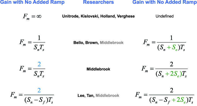
Figure 1 below shows the four different modulator gains, and the researchers that used these gains in their papers.
Figure 1: Modulator Gains from Different Researchers, With and Without Ramp Added
Current Loop Gain Plots
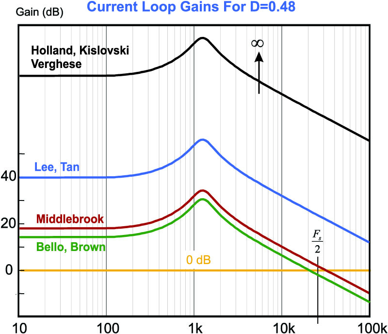
The effect of each of these modulator gains on the current loop gain of the system is shown in Figure 2. Notice that there is a wide disparity in the results. The simplest model, corresponding to the reciprocal of the ramp height, predicts a crossover frequency at about 1/3 of the switching frequency. This is the only model to show that the current loop will cross over below half the switching frequency. Middlebrook’s model crosses over at 2/3 the switching frequency. Lee’s model, and the infinite gain model, cross over at much higher values.
Middlebrook’s model is widely cited in the literature, since his was one of the earliest to analyze current-mode control, but we know from modern sampling theory that this cannot be correct. And yet, the analyses all looked good, so the result was accepted by university researchers and industry.
Figure 2: Plot of Current Feedback Loop Gains
Measured and Predicted Current Loop Gain Plots
While most of the early models predicted a crossover in excess of half the switching frequency, this result was never challenged and never disputed by any measurements. Why? Simply because the current loop gain is very difficult to measure. In most current-mode systems, we do not have a continuously-sampled current waveform, and the only way to make measurements is with a very specialized digital modulator.
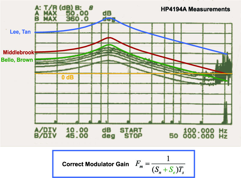
One of these was built at Virginia Tech, originally by Dr. Bo Cho, and an improved version was used to make measurements to compare with the various predictions. The results of this are shown in the gains of Figure 3. There are five different measurements made at a 48% duty cycle, corresponding to each of the black traces. The measurement with the highest gain is with no compensating ramp added. Four additional measurements were made with increasing amounts of ramp to show how this decreased the gain of the loop.
Notice that the highest-gain measurement agrees exactly with the gain predicted by the simple model of Brown and Bello. This is the one that calls out the gain as just the reciprocal of the ramp height. All of the other predictions are proven by the measurement to be too high. They are not correct.
Figure 3: Predicted Current Loop Gains and Measured Results
Where Analyses Went Wrong
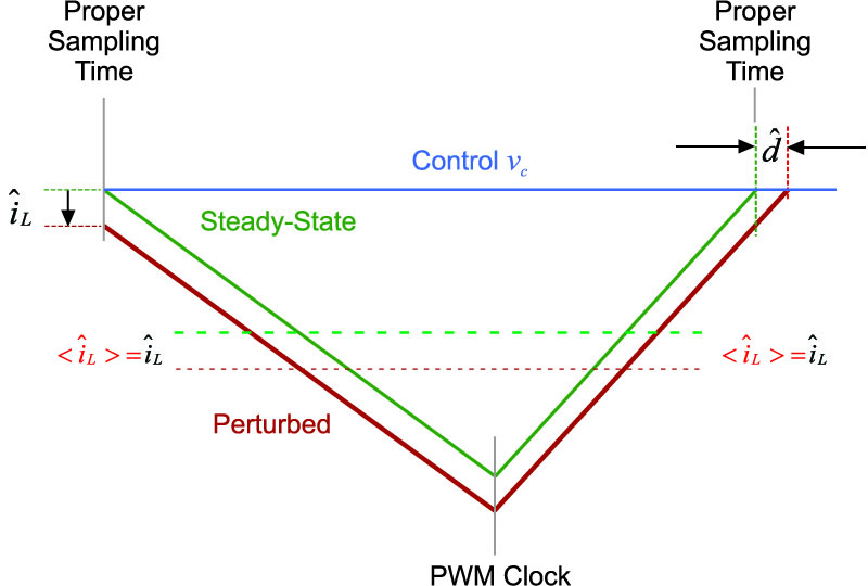
As has been mentioned in this series several times, it is not possible to find a math error in the various papers. That is because there really are no errors in the math. The problem in the different approaches arise from a very critical key assumption about sampled-data systems. For all of the different definitions of average current, the clock of the PWM controller is used as the starting reference point. This is not the correct reference – the sampling of the current waveform does not occur at the system clock. It occurs later at the end of the on-time when the current hits the control reference.
Figure 4 shows the proper timing reference point for the sampling. Once we shift our system reference to this point, a curious thing happens. The perturbation in all of the definitions of current becomes the same, held constant over the full cycle.
Figure 4: Using the Correct Sampling Instant Removes All Discrepancies in the Models
With proper sampling, the initial perturbation in the current is exactly the same as the perturbation for Middlebrook’s definition. He called the average current half of the peak-to-peak current, and since both the peak and valley move by the same amount, the halfway point has the same perturbation. The change in sampling point, and difference in perturbation, explains the factor of 2 error in Middlebrook’s early model.
The same thing happens for the other definitions of average current, including the weighted average definition that previously resulted in an infinite gain.
Summary
In this article, the correct modulator gain has been confirmed by measurement. Under no circumstances can the crossover of the current loop exceed half the switching frequency.
In addition, it is shown that the key assumption that led to different modulator gains arose from selecting the system clock as the initial starting point for analysis. Once the proper sampling time is used as the starting point, all definitions of average current have the same perturbation, and result in the same modulator gain.
It has taken 25 years for this key point to come to light. When I first published my dissertation on current-mode control in 1990, I was under the naive impression that the presentation of measurements versus predictions would put the issue of modulator gain to rest once and for all. This didn’t happen. The measurements were largely ignored and many subsequent papers were published repeating erroneous gains.
Finally, a few years ago, I looked into what caused the errors in modeling, finding the key issue of the wrong sampling instant. I sincerely hope that this will finally end further speculation about current-mode modulator gain, so that researchers and engineers in the industry will finally see some clarity on this issue.
References
- Join our LinkedIn group titled “Power Supply Design Center”. Noncommercial site with over 7000 helpful members with lots of theoretical and practical experience.
- For power supply hands-on training, please sign up for our workshops.
- A Unified Analysis and Design Procedure for a Standardized Control Module for DC-DC Switching Regulators”, F.C. Lee, Y. Yu, M.F. Mahmoud, "A Unified Analysis and Design Procedure for a Standardized Control Module for DC-DC Switching Regulators," Power Electronics Specialists Conference, 1980 Record, pp.284-301.
- “Topics in Multiple-Loop Regulators and Current-Mode Programming”, R.D. Middlebrook, IEEE Transactions on Power Electronics PE-2(2) pp.109 – 124, April 1987.


