


Loop Gains with Multiple Crossover Frequencies
It is common in power design to encounter loops with more than one crossover frequency, as shown in Figure 4. If the loop crosses over multiple times, it is the final crossover (the one at highest frequency) that determines stability.
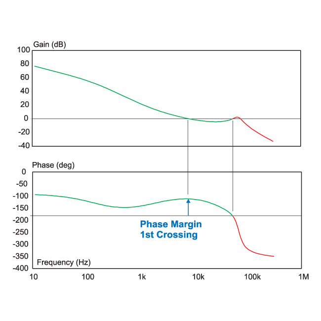
Figure 4: Loop gain measurement with multiple crossing frequencies.
In Figure 4, the phase margin at the first crossover frequency (about 9 kHz) is very good, approximately 65 degrees. However, the loop crosses over two more times, each time with more than 180 degrees phase delay, so this system will be unstable.
There are numerous systems that might have multiple crossings. Three common examples are:
- Current-mode control systems where the subharmonic oscillation is not properly damped with sufficient compensating ramp.
- Converters which have RHP zeros in their control transfer function, causing the gain to flatten out.
- Converters with improperly damped input filters in front of thsub.
For the loop gain of Figure 4, either the shape of the compensation must be changed to prevent the increase in gain at high frequencies, or the crossover frequency must be significantly reduced to avoid instability.