


You can analyze your power supply filter quickly and easily with free downloadable software. This allows you to check for filter impedance interactions, attenuation, and proper damping.
Introduction
This article comes with a free giveaway to help you with your power supply design process. Whether you are designing complete PWM converters from scratch, working with modular power supplies, or something in between, you will be faced with input filter design issues. Once you have read this article, you can download the free program InputFilter.xls to analyze your input filter design quickly and easily.
Is your Input Filter Causing Trouble?
A perpetual problem in designing switching power supplies lies with the input filter. Modern power electronics started with this issue when the very first switching power supplies were built. It was discovered that adding an input filter can make a previously stable system unstable. Much has been written about this in the past, and the reader is encouraged to look at the literature available, starting with reference [1].
With modern dc-dc converters available in either fully packaged form, or as integrated controllers, many new engineers are placing power supplies on a board. The input filter interaction issue continues to plague many designs, especially for engineers who are not familiar with proper design guidelines.
Power supply input filters are used to attenuate switching power supply noise, and to prevent corruption of the input line. If you are designing to meet stringent emissions standards, at least a two-stage filter is needed to attenuate the noise to an acceptable level. If you are designing for board-mount power, and switching substantial currents, at least an LC filter is advised to prevent noise problems on the board.
Figure 1 shows a typical two-stage filter configuration. Two different capacitors are shown on the output of the filter. One provides bulk energy storage, and one provides low impedance at high frequencies.
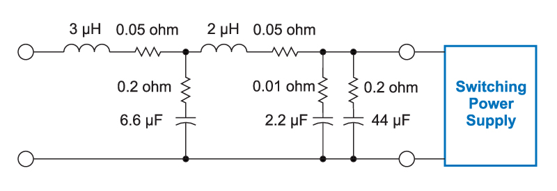
Figure 1: Input filter with five reactive elements.
Input Filter Attenuation
An input filter works in two ways. First, it attenuates noise from the input source to the output of the filter. In this direction, it can be viewed as a voltage filter, and the transfer function is expressed as the voltage ratio from Vin to Vout.
Then, to attenuate the power supply noise, the filter acts as a current filter. The input of the power supply is a switching current, which drives the filter. The transfer function is from the current at the right of the filter to the current at the left of the filter, assuming the input is short circuited (a voltage source.)
In either case, the attenuation is the same. Figure 2 shows the attenuation for the example filter values of Figure 1.
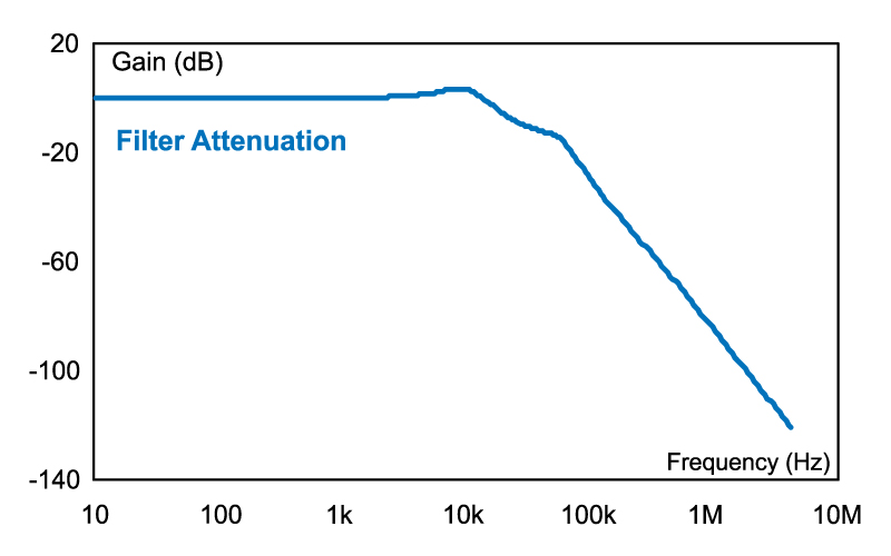
Figure 2: Input filter attenuation.
You will need to measure the noise spectrum before the filter is added to determine how much attenuation is needed to meet your system requirements.
Input Filter Output Impedance
The first requirement of the design is filter attenuation to meet noise specifications. The second requirement is to produce a filter that has low output impedance. This output impedance must be lower than the input impedance of the power supply. If the filter output impedance exceeds the negative input impedance of the power supply, the system typically becomes unstable.
Figure 3 shows the output impedance of the input filter plotted versus the input impedance of a sample switching power supply. It is essential to plot this curve for any design that you do, to be certain that your system will be stable.
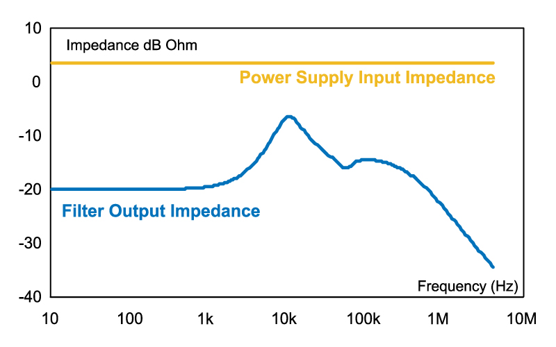
Figure 3: Input filter output impedance.
How do you achieve low impedance? The general rule is to use large capacitors and smaller inductors. Damping must also be included in the filter. This is provided by the series resistances of the inductors, and the ESR of the filter capacitors. Unfortunately, the series resistor in the inductor causes loss, and a high ESR in the capacitor degrades the filter attenuation.
Modern multilayer ceramic capacitors have extremely low ESRs. The filters will be very undamped if these are the only components uses. Experienced power designers will use a combination of different capacitor types to provide the needed filter functions of attenuation, low impedance, and low-loss damping. They will combine high value electrolytics with damping ESRs, and MLCs for bypassing.
Input Filter Design Program
The free downloadable program can assist experienced designers as well as those who are not mainstream designers or power specialists. It is easy to use, and is available on the Ridley Engineering Website.
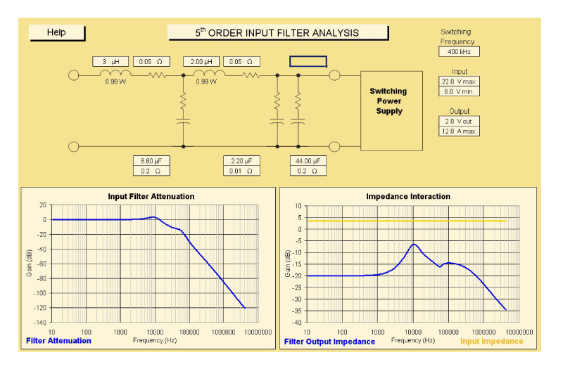
Figure 4: Input filter design program.
Figure 4 shows the design screen of the program. Simply enter your power supply specifications of input and output voltage and power, and then the filter elements. The program allows for a 5th order filter. You build a simpler filter by setting any of the components you don’t want to use to zero.
As you enter the elements, the curves of attenuation and impedance will immediately show the performance of your design. The analytical solutions of attenuation and impedance of the 5th order system are used within the program to provide these curves.
You can certainly use any version of Spice to do the same task, and this can be useful if your filter becomes more complicated. However, you will find that the speed of the Excel approach, and its ease-of-use allows you to design much more rapidly, and without the simulation errors that can occur when working with Spice.
Additional Reading
- Join our LinkedIn group titled “Power Supply Design Center”. Noncommercial site with over 7000 helpful members with lots of theoretical and practical experience.
- For power supply hands-on training, please sign up for our workshops.
- “The Evolution of Power Electronics”