[050] Forward Converter Design - Part XVI Control Modeling

Control predictions and measurement of the five-output forward converter.
Introduction
In this article, Dr. Ridley, the results of measurements of control-to-output characteristics are presented for the multiple-output forward converter. It is shown how to reduce a multiple-output power supply to its equivalent single-output buck converter. Measurements and predictions are compared.
Five-Output Forward and Single-Output Equivalent Circuit
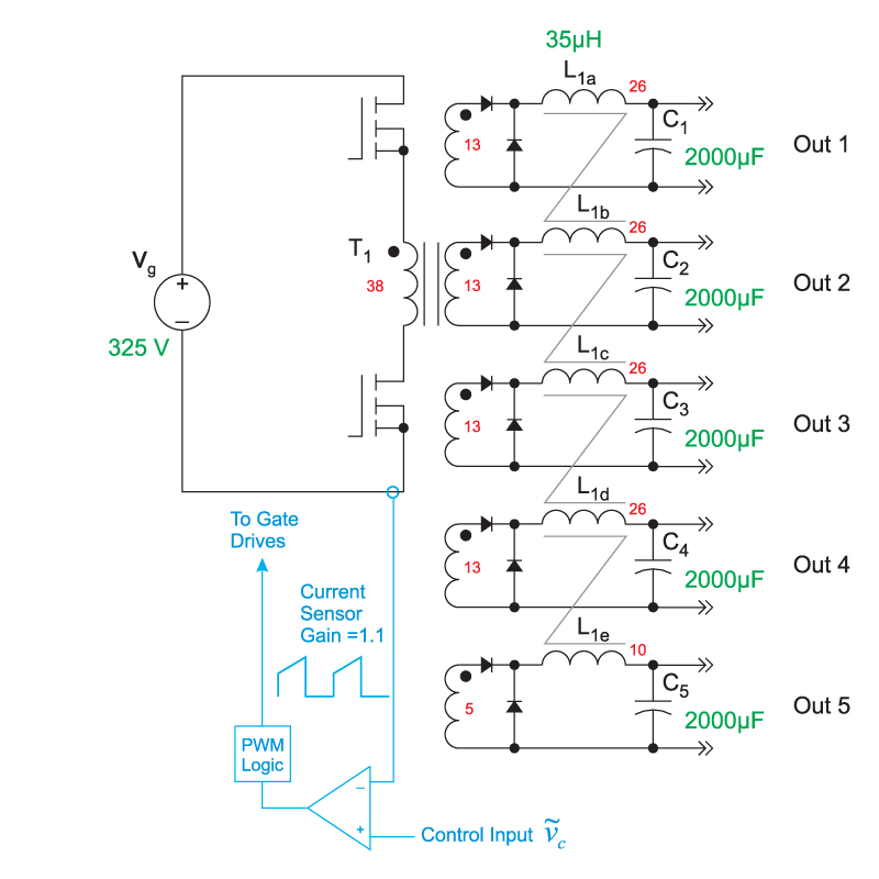
Figure 1 shows the five-output forward converter with coupled inductors. The turns ratios of the magnetics are shown, and these will be used to reduce the converter to a system which can be modeled more easily.
Figure 1: Forward Converter with Five Coupled-Inductor Outputs. Current Feedback is Taken from the Primary Side of the Circuit.
The primary current is sensed as described earlier in this series of articles, and is scaled by 1.1 to provide the voltage signal for the feedback comparator.
There are very few articles which deal with the small-signal characteristics of multi-output converters. As will be seen later, there are complexities of multiple outputs which are difficult to model exactly.
The first step in arriving at the transfer functions for the circuit is to reflect all of the output components to the output which will be regulated. For this circuit, the 12 V output goes to the feedback controller, so all output capacitor values and load resistor values are reflected through the inductor and transformer turns ratios to arrive at the equivalent model shown in Figure 2.


