


[055] Manual Frequency Response Measurements for Magnetics - Part I
How to measure your magnetics properly with a minimum of test equipment.
Introduction
In this article, Dr. Ridley describes how you can make frequency response measurements of transformers and inductors using equipment that you probably already have in your laboratory. This is very important for students and very small companies who cannot afford the sophisticated equipment needed for more serious production level work and for high-speed development.
The Importance of Impedance Measurements
While still a student at Boston University, I was fortunate to enroll in a machines class which was taught in the Franklin Institute. The course was very hands-on, involving ac motors, transformers, and generators, in a laboratory that had been in place for decades. To this day, I clearly remember many aspects of the lab due to the immediate and interactive nature of the experiments.
One of the first things that we did in the lab was to plot a transfer function of transformer and motor windings in order to extract important equivalent component values needed for design and analysis. This process was always a fundamental first step in doing any experimental work. The experiments were performed using basic laboratory equipment, using an analog signal generator and analog oscilloscope.
Once I started work in power supply design, I applied the same philosophy when building hardware. All magnetics should be properly characterized over a wide range of frequencies in order to extract important parameters. During the design phase, these parameters are very important. Later on, during the transition from design to manufacturing, the characteristic frequency response curves are a powerful and sensitive tool to determine proper construction of magnetics.
Ideally, the measurements of magnetics impedance should be made with a properly calibrated and automated piece of test equipment [1]. However, many students of power electronics, and engineers just starting their careers or their own companies do not have access to anything but the most basic of laboratory instruments. Even in this situation, it is highly recommended that the impedances of magnetics be properly measured and recorded. It may be a time-consuming process, but it is very important for understanding of your circuit, and repeatability of design.
Manual Setup of Impedance Measurements
Figure 1 shows the recommended test setup for measuring magnetic components. The device under test is connected in series with a 1-ohm test resistor, and a signal applied across the series combination. The voltage across the 1-ohm resistor, representing the current, is measured with one channel of an oscilloscope, and the voltage across the series combination measured with the second channel.
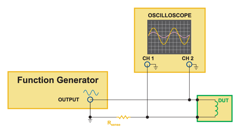
Fig. 1: Schematic of how to measure frequency response of magnetics using a signal generator and oscilloscope.
Figure 2 shows a photograph of the actual lab test setup. A small test fixture containing the sense resistor was used to improve RF layout issues of the test setup.
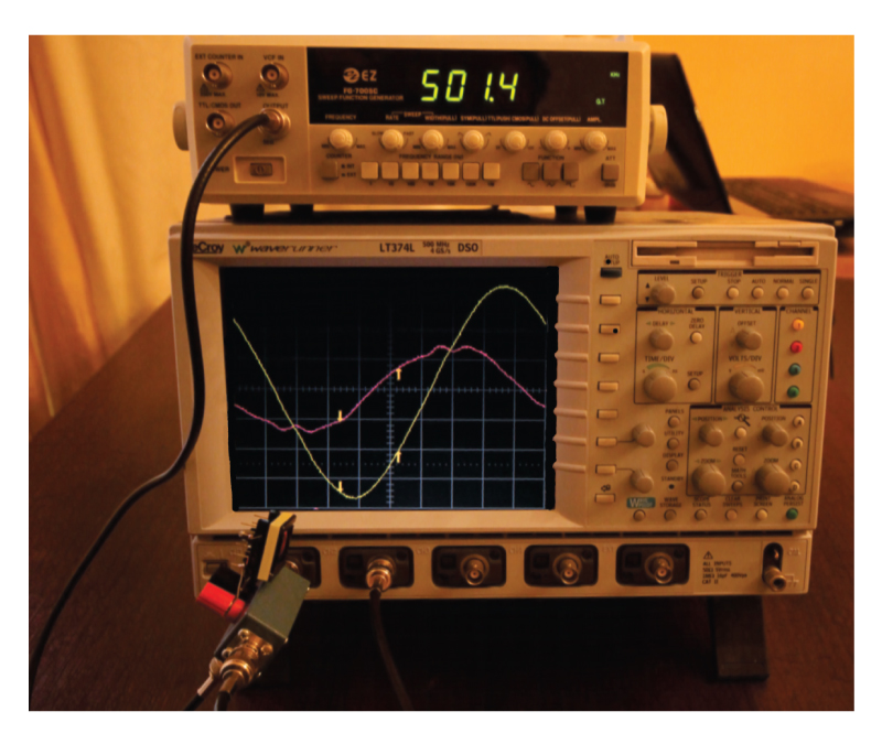
Fig. 2: Photograph of manual magnetics impedance test setup.