


Designing noise filters on the output of power supplies, and using proper probing techniques to measure low levels of noise.
Introduction
Switching power supplies are inherently noisy. Large amounts of EMI are generated on both the input and output sides of the switching converter, and in most designs, the noise is not well characterized or controlled.
Switching Power Supply Noise
High-frequency switching power devices and diodes generate large amounts of EMI in all switching power supplies. On the input side of the converter, there are stringent limits on the noise that may be carried back to the AC power line, and these limits are extraordinarily low. The only way to meet the emission specifications are with two- or three-stage filters, carefully selected to attenuate the measured noise, and properly damped to avoid instability [1]. Both common-mode and differential mode filters are used to pass the EMI testing criteria.
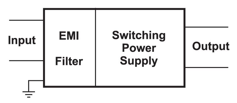
Figure 1: Power supply with EMI filter on the front end.
However, most power supply specifications for output noise are very poorly defined. People refer to peak-to-peak noise, rms noise, but rarely do they specify the noise in the same stringent way as the input. As a result, most switching power supplies put irresponsible amounts of noise on their output leads.
For many loads, this is not an obvious problem – the loads are either insensitive to the high-frequency noise, or they have been bypassed with capacitors to clean up the rails at the point of use.
There is no reason for power supplies to be so noisy on their outputs. Simple application of multistage filters provides very clean output with minimal cost, and should be applied in most situations. As microprocessor voltages drop, the susceptibility to noise increases, and the risk of weak standards on output noise are not worthwhile.
Measurement of Output Noise
Most engineers assess the output noise of their converter with an oscilloscope. A spectrum analyzer, used as for the input noise, would be more appropriate, but this is rarely done.
If you are going to use an oscilloscope to measure the noise, there are several precautions that must be taken. Figure 2 shows the standard oscilloscope probe test leads. A ground lead approximately 10 cm long clips to the ground of the circuit, and a spring-loaded barrel on the probe hooks on the test point. I always use the oscilloscope on its maximum bandwidth for these measurements to ensure that I am seeing all the components of the output noise.
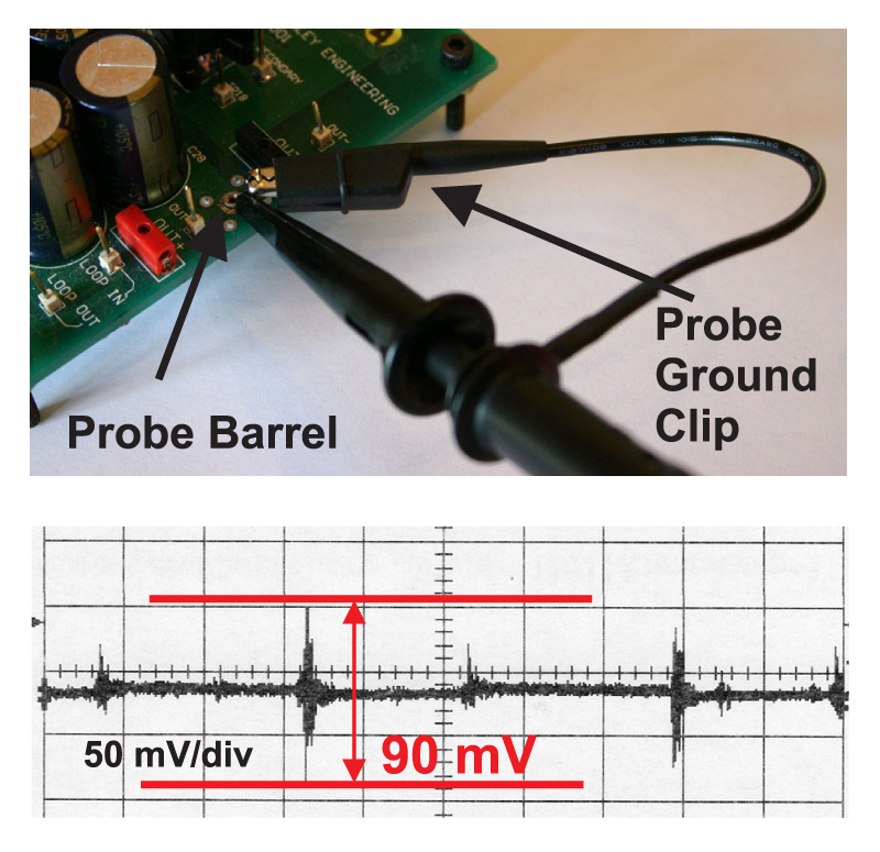
Figure 2: Oscilloscope probe with standard setup, residual ground noise.
Using this test setup, the first thing to do is measure the residual noise being picked up by the probe. That is done by connecting the probe tip to the same ground point as the ground clip. The waveform in Figure 2 shows that this test setup is not effective at removing the residual measurement noise. There is 90 mV peak-to-peak.
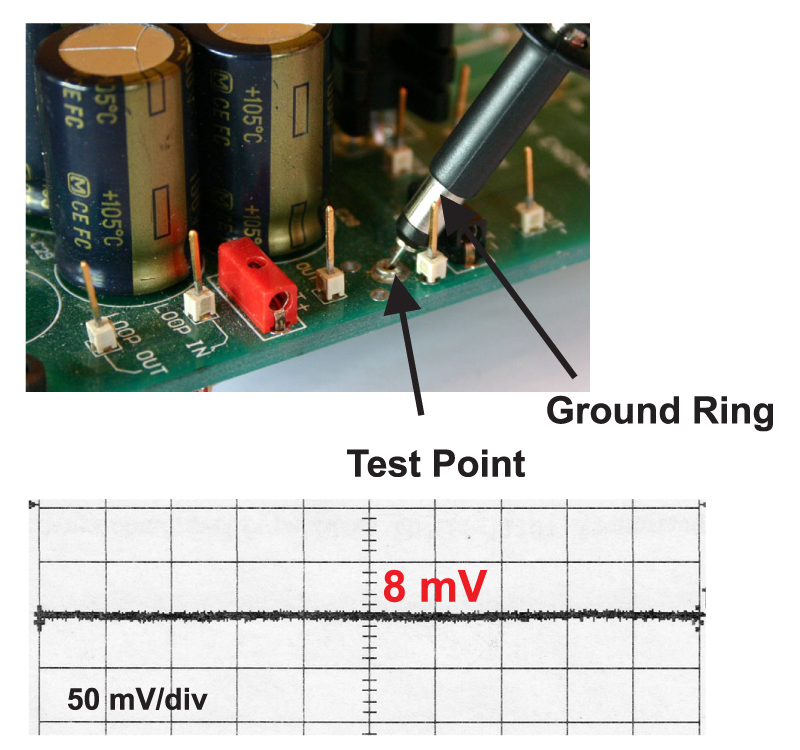
Figure 3: Oscilloscope probe with probe tip and ground lead removed.
Figure 3 shows the same oscilloscope probe with a proper setup for low-noise measurements. Both the probe barrel and the ground lead have been removed from the probe. There is a ground ring around the shaft of the probe, and this is grounded as close to the test point as possible. This setup reduces the noise in the measurement to just 8 mV, low enough for most output noise measurements.
This setup reduces noise pickup by minimizing the loop of the earlier connections. This loop acts as an antenna picking up stray magnetic fields. The smaller probe tip, and elimination of the ground clip also minimizes surface area, and this reduces electrostatic field pickup.
You must also be careful with the routing of the cable from the probe to the oscilloscope. Figure 4 shows how the noise pickup is increased to 30 mV when the lead is run too close to the switching devices of the power stage.
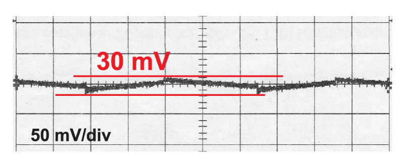
Figure 4: Increased noise pickup with improper routing of probe cable to oscilloscope.
There is one more suggestion that has appeared recently in some semiconductor applications notes. They recommend soldering a couple of capacitors across the oscilloscope probe tip. While this will no doubt reduce the noise measurements, it will not have any meaning since you have introduced a second stage filter in the system. You should never characterize your system with additional capacitors across the instrumentation – the results are simply wrong.
When you are preparing to measure your power supply, take these steps first to make sure you have a good clean background when you make the ground measurement.
Filtering the Output Noise
Flyback converters are popular for many different applications, ranging in power from fractions of a watt, to about 50 W. The flyback converter has the disadvantage of a pulsating current on the output of the transformer. The current pulses are absorbed by the output capacitor, and the fast-rising edges give rise to considerable noise, as shown in Figure 5.
Figure 5: Flyback converter output voltage noise.
The noise in this figure is for a 24 W flyback converter operating in continuous conduction mode, and switching at 100 kHz. The peak noise is about 280 mV, using 880 µF of output capacitance. Notice that there is wideband frequency content in the noise spectrum starting at 100 kHz, and extending into many tens of MHz for the noise spikes.
There is no reason to tolerate this level of noise from your switching power supply. A simple 2-stage filter can provide drastic reduction as shows in Figure 6.
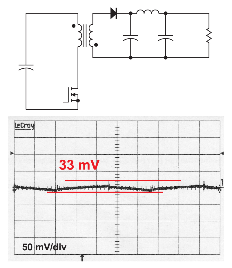
Figure 6: Flyback converter with two-stage filter
To build a two-stage filter, the output capacitor is split (usually into approximately equal parts) by a small inductor. The rules for selecting the inductor and filter parameters are covered in detail in [2]. In this particular example, the inductor was physically equal to about 25% of the volume of the output capacitor bank. The effect on the output noise is dramatic. The peak-to-peak noise level is now only 33 mV, almost a ten times reduction.
The two-stage filter is undoubtedly a more complex system, but with careful attention to the design rules, it is not that difficult to implement, and the system remains stable even if the feedback point is taken from the output of the power supply.
Summary
Almost every switching power should incorporate at least a two-stage filter on the output to reduce the noise. In high-performance systems, there should also be common-mode filtering, just as for the input filter design. Do not be tempted to skip this crucial part of the design.
Remember when looking at output noise to make sure you have your instrumentation set up properly. Always test the residual ground noise measurement before looking at the output noise.