


Design and testing of rugged current limiting for the forward converter.
Introduction
This article continues the series in which Dr. Ridley documents the processes involved in taking a power supply from the initial design to the full-power prototype. In part VI, attention is turned to implementing proper current limiting to ensure a rugged power supply under all conditions.
Primary Current Sensing
In Parts IV and V of this series of articles [1], voltage spikes were properly controlled on both the primary and secondary of the power supply to prevent failure of the power semiconductors. With this done, the power supply can be taken up to full input voltage, and full load on the output.
It is tempting to do a substantial amount of data collection at this point to make sure the power supply is regulating properly, and to test parameters such as efficiency, regulation, and thermal rise. However, it is advisable to move on to a phase of testing that most designers do not look forward to – current-limit testing, and short-circuit testing to make sure the power supply is rugged.
Many engineers leave the short-circuit testing until the end of the power supply development. Experience tells them that this is often a destructive and time-consuming process, and they are reluctant to damage their first prototype so early in the testing process. However, it should be done immediately. Changes to the current-limiting and current-sensing circuits may lead to power component changes in order to survive short-circuit testing.
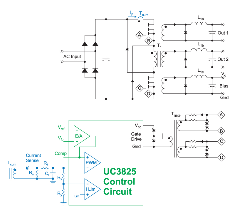
Figure 1: Two-switch forward converter with current sensing network. Current sensing components are shown in blue in this figure. It is recommended that a converter have two levels of current sensing – one for normal peak current limiting, as part of the main PWM control loop, and a second level for short-circuit protection.
The UC3825 control chip provides for two levels of current protection. The first level is implemented in the main PWM comparator, and the error voltage from the voltage feedback sets the peak current level on each cycle. This error voltage is clamped to around 4.5 V, providing a fixed limit to the current regardless of the state of the output voltage. However, this current sensing mechanism also has leading edge blanking, and for the first few hundred nanoseconds, the signal is ignored.
The filtered current sense signal is also divided by resistors Rx and Ry in Figure 1, and this is fed into the second current limit input, which has an immediate response when the signal exceeds the threshold of ILim. No leading-edge blanking is applied on this input, allowing for fast protection during short circuits.
Power Supply Startup Current Waveforms
The first instance of current limiting normally occurs during the startup of the power supply. Initially, the output capacitor of the power supply is discharged. For a few milliseconds, the capacitor looks like a short circuit. The severity of this test depends on the settings of the soft-start circuit. If the soft-start is very slow, current limit may not be encountered during start-up. With a faster soft-start, current limiting will be encountered during the turn-on process.
Figure 2 shows a waveform of the primary switch current during turn-on of the power supply. This is a waveform with a characteristic that you will hopefully not see in your power supply. There is a distinct curve at the top of the yellow waveform, showing that the power magnetics are saturating. A well-designed converter should never exhibit this characteristic under any test conditions.
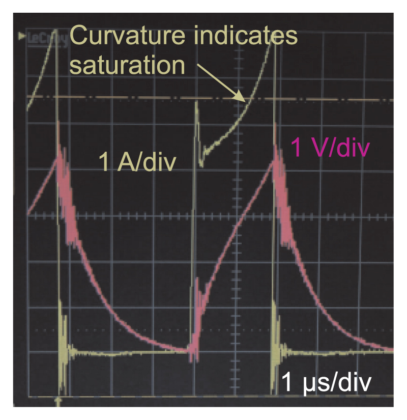
Figure 2: Current-sense waveform with abrupt application of input voltage, and output capacitors discharged. Soft-start provides protection in addition to the current limiting. However, magnetics saturation is clearly visible in the current waveform. The red waveform shows the filtered current signal after the components Rf and Cf.
There are two magnetics in the forward converter that can saturate – the power transformer, and the output inductor. Figure 3 shows a diagram of the components of the current sense waveform on the primary of the forward converter. The current transformer senses the reflected output inductor current, plus the magnetizing current of the power transformer. When looking at the waveform of Figure 2, you cannot initially tell which of the two magnetics is saturating.
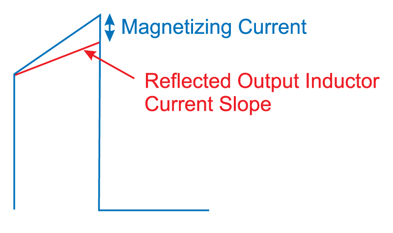
Figure 3: Components of primary current, showing contribution of magnetizing current of transformer
The output inductor and the power transformer are saturated through two different mechanisms. The output inductor saturation depends upon the current flowing through the main inductor to the load. Transformer magnetizing saturation depends upon the input voltage and duty cycle, not upon the load current.
When the current sense resistor, Rs, is increased to 68 ohms from 47 ohms, the peak current is reduced, as shown in Figure 4 (notice the change of the vertical scale). The saturation characteristic is completely eliminated. This shows that the output inductor is the component that was saturating, not the power transformer.
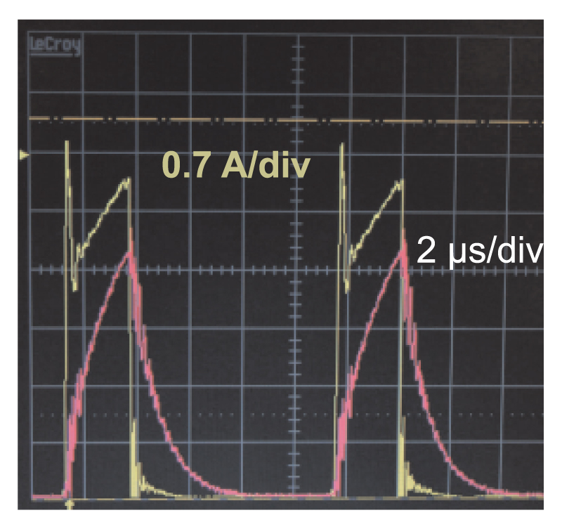
Figure 4: Increased current sense resistor (reduced current limit level) eliminates saturation. This shows that the output inductor is saturating, not the power transformer.
With the startup waveforms corrected with the increase current sense resistor, short circuit testing can now be done.
Short Circuit Current Waveforms
One of the harshest tests to a power supply is to place a short circuit on the output, and to abruptly apply high input line voltage. The power supply controller ramps up the current through the soft-start period, then cuts back to a very small duty cycle to protect the power switches. A well-designed converter should survive this test, and it must be done early in the design process.
To avoid too much destruction, it is a good idea to monitor the primary current, and perform this test starting at low line, and gradually increasing the line voltage. It may be necessary to adjust the filter components and the divider resistors in the current sense network during this process to achieve the proper degree of protection.
Figure 5 shows the current sense waveform under short-circuit conditions. The current pulse is cut back to just 100 ns before the gate drive is turned off. This is well within the leading-edge blanking time of most PWM controllers, which is why a second current-limit level is recommended. Once this higher current level is reached, a soft-start sequence is initiated by the controller after a substantial time delay of several milliseconds. This protects the converter components.
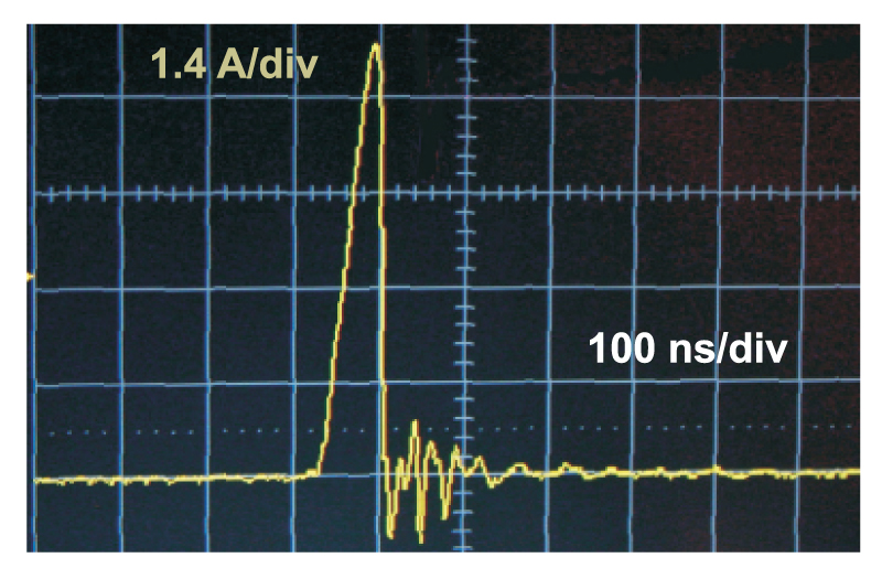
Figure 5: Current sense waveform with high-line voltage input and short-circuit on output. Notice that the current pulse is reduce to just 100 ns. When this current signal exceeds a second current limit threshold, soft-start is reinitiated, and the converter enters a burst mode of operation at low frequency, protecting the semiconductors from overstress.
While it is painful to do this test early on, you will find that once you have set the current sensing properly, you feel much more confident about the ruggedness of your design, and you can move on to the next stage of testing.
Summary
The final stage of protection of the power circuit is not in place. Rugged current limiting will protect the semiconductors under all test conditions without any failures.
So far, the power stage testing has followed this order:
1. Check gate drive circuit waveforms.
2. Test primary circuit with resistive load.
3. Insert magnetics into circuit and verify low-voltage waveforms.
4. Design proper voltage clamps on primary switches.
5. Design proper voltage clamps and snubbers for secondary diodes.
6. Design proper current sensing circuits, test for startup and short-circuit.
The circuit is now ready for use at full power and the full range of test conditions.
During the six steps listed above, and described so far in this series of articles, there have been multiple modifications to component values, board connection changes, and other additions and corrections. At this point in the development cycle, it may be wise to redo the PCB layout to accommodate all of these changes. Or, if time is an issue, testing can continue with the present PC board. For an experienced power designer, there are normally a minimum of three PC board iterations. Choosing the right time to turn the board is important. It is desirable to delay the PCB change to work as many changes into the second iteration as possible, but at some point, the number of jumpers and changes will force the issue.
For this example of a two-switch forward, further testing was done before revising the PC board layout.
References
- Join our LinkedIn group titled “Power Supply Design Center”. Noncommercial site with over 7000 helpful members with lots of theoretical and practical experience.
- For power supply hands-on training, please sign up for our workshops.
- 1. “Power Supply Development Diary Parts I-V”, www.ridleyengineering.com/design-center.html
- “A New Small-signal Model for Current-Mode Control”, Raymond B. Ridley,1990 PhD dissertation, free download is available.