How to arrange the components of your second-stage output filter for optimum performance.
Introduction
Dr. Ridley demonstrates how the proper configuration of a second-stage output filter can significantly lower the output impedance of your power supply. The correct arrangement of components is essential for optimal performance, and is often overlooked.
Output Filter Configurations
A powerful design technique for reducing the noise on the output of a switching power supply is to utilize a two-stage output filter. Dramatic reductions in noise can be obtained with small filter components. If the design is done properly, the filter can be incorporated into the main feedback loop for optimal regulation.
Figure 1 shows the schematic of a 1 kW boost converter, operating at 75 kHz. Notice that there are two different types of output capacitor, one used for bulk energy storage, and one to provide low impedance for the high pulses of current that flow in the output capacitor.
Figure 1: Boost Converter with Two Different Output Capacitors.
While the two-capacitor approach to an output filter works reasonably well, it is far more effective to incorporate a second-stage inductor between the two capacitors to attenuate the noise further. Figures 2 and 3 show two different ways to configure the output filter using a 300 nH inductor.
In Figure 2, the large capacitor is on the left, and the small capacitor is on the right. In Figure 3, the position of the capacitors is reversed. Both of these arrangements produce similar power-stage control and attenuation characteristics, as analyzed in [1] and [2], and at first glance appear to be equivalent.
Figure 2: Two-Stage Output Filter with First Capacitor Larger than Second Capacitor.
Figure 3: Two-Stage Output Filter with First Capacitor Larger than Second Capacitor.
Some designers consider the second capacitor and filter to be a noise filter, and therefore simply use small values for the second inductor and final capacitor. However, as we will see later, this is not the best configuration for the second filter.
Power Supply Output Ripple
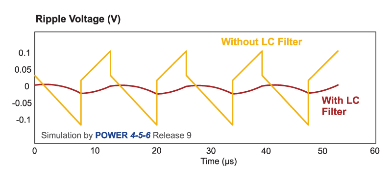
Figure 4 shows the simulated output ripple with the second-stage LC filter in place. The gold waveform shows the ripple without the second inductor, and the red waveform shows the ripple after the inductor is added. Even though the second inductor is only 300 nH (about 5% of the value of the main inductor), the second filter provides a 20 dB reduction in output noise. Clearly, the use of a two-stage filter is very beneficial.
The effect on very high frequency noise spikes, not shown in this simulation, can be even more dramatic.
Figure 4: Simulated Output Ripple Voltage with Second-Stage Filter.
Loop Gain with Second-Stage Filter
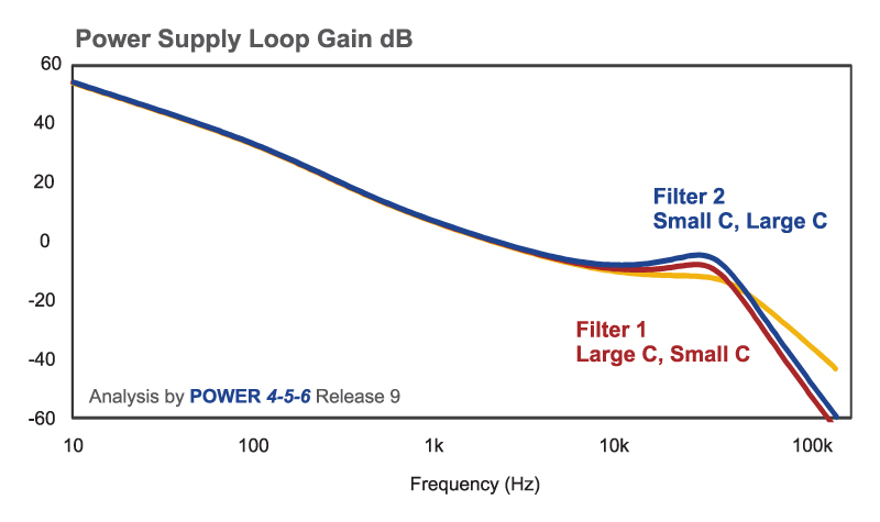
Many designers worry that the additional poles and phase delay of a second-stage filter will compromise the loop stability. Figure 5 shows the loop gain of the system with and without the second stage filters. The gold curve shows the loop gain without the second inductor, and the red and blue curves show the loop gains with the two different configurations of output filter.
The two filter configurations have almost identical loop gains, and there is not significant stability difference between them. It can also be seen that there is plenty of phase margin in the system when the filters are added.
Figure 5: Effect of Second Stage Filter on Current-Mode Loop Gain.
Output Impedance with Second-Stage Filter
It has been shown so far that the two different configurations of filter have almost identical attenuation characteristics and stability. However, they are dramatically different when we look at the output impedance of the power supply. Output impedance is measured by injecting a current source into the output of the power supply, as shown by the components in green in Figure 1.
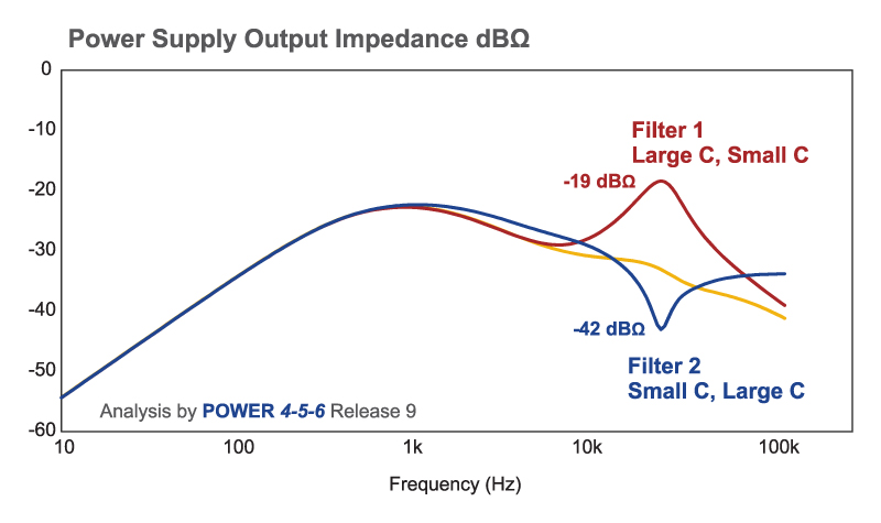
The output impedance for each of the three filter configurations is shown in Figure 5. The gold curve shows the filter of Figure 1 with two capacitors, and the red and blue curves show the output impedance with the two different arrangements of the capacitors on either side of the second inductor.
Figure 6: Closed-Loop Output Impedance with Different Filter Designs
The curve in red shows the impedance obtained when the first capacitor is large, and the second capacitor, closest to the load, is small. The peak of the output impedance at the second resonant frequency (about 30 kHz) is more than ten times higher than the output impedance of the other filter configuration, shown in blue.
The optimal configuration of the filter, with the small capacitor followed by the large capacitor, has a dip in the output impedance at the second resonant frequency. This is clearly a much better arrangement for the filter components.
The use of two different types of capacitor is quite common for high-power systems where performance is paramount, and higher quality components are possible within the budget. Electrolytic capacitors are usually used for the large bulk capacitors, and film capacitors for lower value, low ESR capacitor.
For lower cost power supplies, the usual technique is to use the same type of low-cost capacitor throughout, splitting them approximately equally between the first capacitor and the second.
Summary
Two-stage filters are a powerful design tool used by advanced power supply designers. They provide dramatic reduction of noise, and can be incorporated into the feedback control loop if properly designed.
The design verification process should always include output impedance measurement of a power supply. This is the parameter that will have a strong dependence on the arrangement of the second filter components. When using different types of capacitors for an advanced filter, it is best to put the smaller value of capacitor first, and the large value of capacitor next to the load.
Additional Reading
- Join our LinkedIn group titled “Power Supply Design Center”. Noncommercial site with over 7000 helpful members with lots of theoretical and practical experience.
- For power supply hands-on training, please sign up for our workshops.
- “Secondary LC Filter Design Techniques for Current-Mode Controlled Converters”, Raymond B. Ridley, IEEE Transactions on Power Electronics, October 1988.
- “Second-Stage LC Filter Design”, Ray Ridley, Ridley Engineering
- All waveforms and transfer functions in this article were generated by POWER 4-5-6 Release 9, available from www.ridleyengineering.com .
- Techniques for measuring output impedance can be found under the analyzer section of www.ridleyengineering.com .


