


Digital power is all the rage now, but don't expect it to shorten your design time, or to eliminate the need for complete optimization of the analog parts of the power supply.
Introduction
At the recent Applied Power Electronics Conference, digital power supplies were featured everywhere, in papers, seminars, and poster sessions. Applications were widespread, in VRMs, power factor correction circuits, inverters, and dc-dc converters.
It’s easy to start feeling overwhelmed with all this information on digital applications. And, in reading the material, to feel like you are perhaps missing the boat with your simple analog solutions. In this article, I’ll examine some of the issues and misconceptions about digital control.
Digital Control is New?
Figure 1 shows the block diagram of a digital controller. At the input side, an a/d converter samples an analog waveform of the power supply, and converts it to a digital value. The analog waveform may be the output voltage, or some pre-processed waveform where it has already been compared to a reference.
Sampling is done carefully, in an effort to avoid switching noise from affecting the results, and this simple sampling process can be quite complex, especially if there are multiple converters operating together in a system.
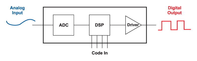
Figure 1: Block diagram of Digital Controller
The resulting digital signal then enters the processor of the digital controller, which sends the gate drive to the system. The driver circuitry may or may not be included in the controller, and this was discussed in the December 2006 issue of this magazine.
Much of the focus in recent years has been concentrated on solving the issues of the resolution of the digital output pulse. Numerous researchers have come up with solutions, including delay gates, to provide resolution beyond the clock frequency of the digital controller. This is important to avoid numerical oscillation.
Now let’s look at the so-called analog controller—yesterday’s technology if you listen to all the digital papers. Figure 2 shows a typical controller. The output voltage of a converter is processed with an analog amplifier, and discrete analog parts are used to compensate the feedback. The output of the error amplifier then is compared to a ramp with a comparator. The ramp also forms the clock of the converter.
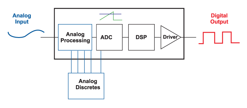
Figure 2: Block diagram of “Analog” Controller
The ramp-reference circuit is nothing more than a simple A-D converter, directly generating a digital waveform, and setting the width of the pulse at the output of the controller. If you look at the input and output waveforms of Figure 1 and Figure 2, one thing should be immediately obvious: the analog controller that we have used for over 20 years in this industry is, in fact, a digital controller!
It has all the features required—and ADC, digital processing circuitry, and digital output. It is also an incredibly elegant solution to the digital controller problem. The clock frequency does not need to be any higher than the desired switching frequency of the power supply, and yet the output digital pulse has infinite resolution. This is something the new digital controllers are still struggling to achieve.
It is very important to recognize that the controllers we’ve always used are digital controllers. It stops us from worrying about whether we are using the latest in technology—analog or digital—when in fact they are both digital with different implementations. And it moves us forward to consider what the real difference is between the old and new, and whether you need it.
The core difference is that the new controllers are programmed with software, whereas the old controllers are hard wired, and not as flexible. As we’ll see in this article, the capability to reprogram may not be as important as claimed for your converter.
Digital and Analog Loop Gains
Papers on digital control invariably focus on the perceived advantages of the new controllers, and often make unfavorable comparisons to analog controllers. (I’ll use that term here in order to be consistent with the industry, although we now know that they are all digital.)
The first area of comparison is in looking at control design, and transient response. The digital controllers are advertised as being easier to customize, providing better transients, and push the converters to the limits of their capability.
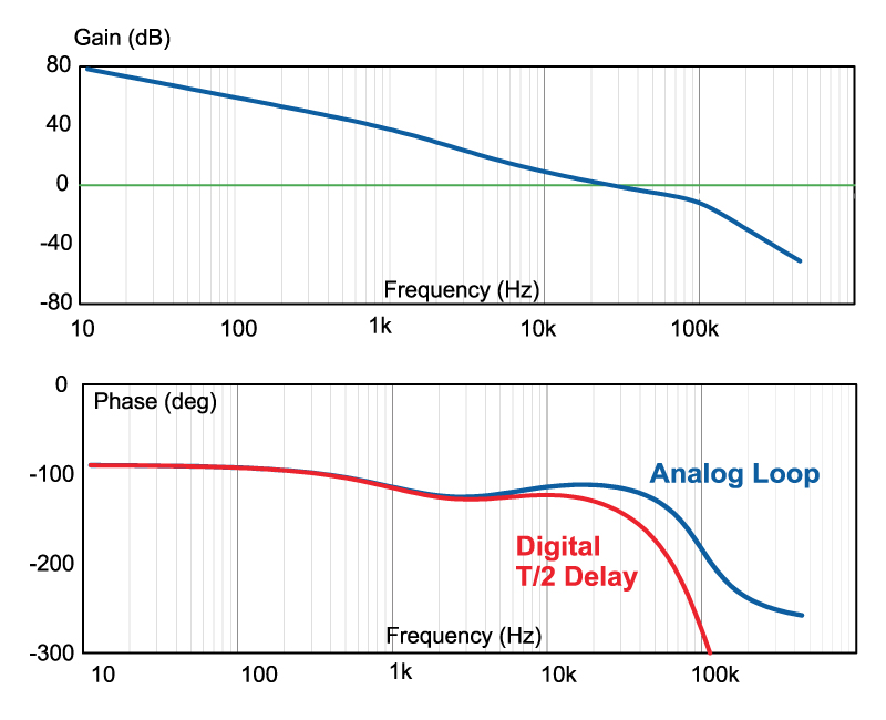
Figure 3: Loop Gain with Analog and Digital Controller
Figure 3 shows the loop gain of an analog-controlled power supply, compared to that of a digital power supply. (Yes, you still need to make a good old analog bode plot of the loop of a digital system to assess final performance.)
Notice that the loop gains are very similar, except that the phase delay of the digital power supply is greater than that of the analog power supply. This is due to the delay from sampling of the output voltage to the time when it is used. Long ago with analog controllers, it was recognized that a naturally-sampled modulator was superior in performance to a sample-and-hold function.
According to these curves, the analog controller is actually superior in small-signal response. Proponents of digital will argue that the digital controller can be programmed to override the small-signal response any time the output moves outside a preset boundary, but is that necessary? We can look at the step load response to answer this.
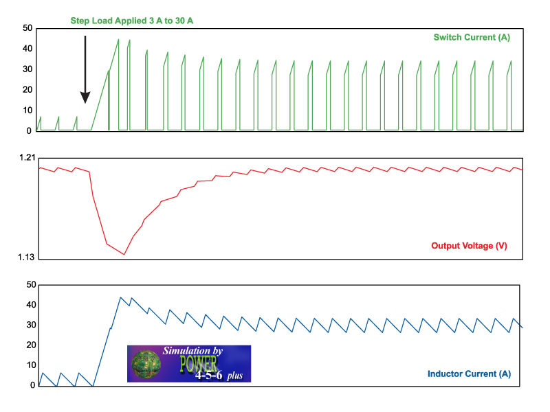
Figure 4: Step Load Response with Analog Controller
The analog loop shown here has a crossover frequency of 25 kHz—one-eighth of the switching frequency. Figure 4 shows a 10% to 100% step load for a buck converter. Some papers make wrong assumptions about loop gains, saying that for this particular converter with a 1/8 switching frequency loop crossover, it will take about 8 switching cycles for the converter to respond. However, you can see that this is clearly not true. Within one cycle of the step load being applied, the duty cycle of the control chip moves to its maximum value, and the drop in the output voltage is halted quickly. This is easy to achieve with the analog controller.
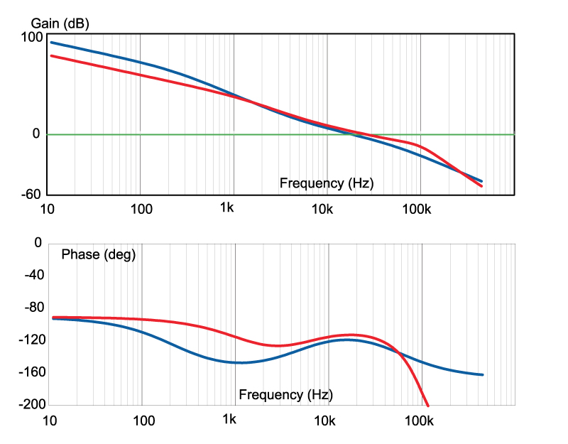
Figure 5: Loop Gain with Analog Controller in DCM and CCM Mode
How about ruggedness? A touted feature of digital control is its adaptivity to different modes of operation. For example, crossing the boundary of CCM (continuous-condution mode) and DCM (discontinuous-conduction mode) operation could be detected, and controller parameters changed. However, as we see in Figure 5, the application of simple current-mode control achieves the same desired effect with an analog controller with minimal cost and effort. The loop gain of the converter is optimized regardless of the mode of operation.
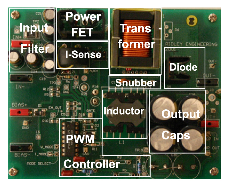
Figure 6: Switching Power Supply with Controller
How Will Design Change?
At last year’s APEC, I was told by an engineer from one of the semiconductor companies that digital control would greatly simplify the design task. In effect, it would eliminate the need for the specialized power electronics engineer (or at least, that’s what I inferred was being said), and anyone could design a power supply. He even claimed that the controller would soon be able to measure the power supply while operating, constantly adapting parameters without any input from a designer.
What is the truth? How much would such a power controller really help the power supply development task? Take a look at Figure 6, which shows a typical dc-dc power supply rated for about 100 W output. The control chip takes up perhaps 10% of the surface area of the board. During the design procedure, much time is devoted to magnetics, board layout, snubbers, thermal problems, cross-regulation, EMI, filtering, and ruggedness. Compliance testing and EMI testing alone can take weeks or months of development time.
Figure 6: Switching Power Supply with Controller
Digital control chips offer nothing to short-circuit this time consuming process of power supply development in these areas. When it comes to closing the control loop, we do get a difference. In place of discrete analog compensation parts, software replaces this task. But the compensation task is perhaps a few hours out of a complete design cycle when you know what you are doing. The digital controller will actually make this process longer due the computer interfacing needed, and you’ve still got to verify the results with extensive loop measurements under all conditions.
Where will Digital Help?
So is digital control unnecessary? Well, that depends on your application. If you have a straightforward dc-dc converter, you probably have no need for a software interface in the middle of your power supply. It will offer little or nothing to speed up your design or improve performance, and it will certainly be more expensive.
However, if you have a complex power system where you are processing data for multiple converters, for example, the digital controller can be essential. This is certainly the case for high-current point of load converters where multiple phases must be controlled in parallel with precise current sharing, shifting output voltages according to processor requirements, and PM bus communication.
So keep your eye on digital developments. Remember, you are already digital, and you already can achieve excellent performance. You are just trying to decide whether you want the burden and potential flexibility of software in the control loop to handle complex processing tasks that can become difficult with classic analog controllers.
In my career over the last 25 years, I have seen two other topics hit our industry and catch its attention like digital is doing. The first was the boom in research , and the second was the resonant converter frenzy in the 1980s. Both of these left behind some good solid technologies that filled certain niches, but left much of the world of power supply design intact. I suspect that digital control will do the same.
It has already penetrated the specialized niche of VRMs. It is trying to penetrate the world of PFC where analog can struggle with the complex functions needed. They will find some penetration here, but not without a fierce struggle from new analog controllers with novel solutions to the problem.
And in the world of “real” power—offline converters above 100 W, I would expect ultimately to see a class of controllers that combine the communications of digital with the necessary fast response of analog control features in the innermost modulation and protection loops.