


The changing characteristics of the capacitors used in power supplies are examined. They are not as simple as most engineers assume.
Introduction
In several past articles, we have examined some of the complex characteristics of the power magnetics of a switching power supply. In this article, we examine another major passive component of the power supply—the capacitor. This is often a component that is viewed as a simple part that doesn’t require too much attention.
In this article, we examine another major passive component of the power supply—the capacitor. This is often a component that is viewed as a simple part that doesn’t require too much attention.
Power Supply Capacitors
Figure 1 shows the simple buck converter. Given modern integrated controllers, the design task of the engineer is apparently very simple—all we have to do is select and inductor and two capacitors, and the job is done. The choice of inductors can become very complex, and now we’ll see how capacitors can be troublesome, too.
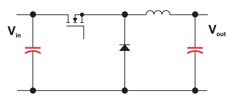
Figure 1: Buck converter with critical capacitor components. The output capacitor impedance determines the mid- and high-frequency response of the converter using either voltage-mode, current-mode, or any other form of control, including digital.
I’m often asked to perform worst-case analysis of switching power supply designs like this for companies. Step one of this process usually consists of the company sending me schematics, parts lists, and component data sheets. Before proceeding further, I always have to ask for working physical samples of the power supplies to test on the bench. To the alarm of people not familiar with power supplies, much of the worst-case analysis depends on measurements of existing designs, combined with documented datasheet variations which will shift the design.
Component data sheets are rarely adequate for properly characterizing parts, and a comprehensive analysis requires information either not readily available from manufacturers. Additional measurements are needed for magnetics, and additional measurements are needed for capacitors, too.
Low-Impedance Capacitor Measurement
A simple fixed RLC tester with a single measurement frequency is not adequate for characterizing capacitors for use in a modern switching power supply. The capacitors must be measured over a wide range of frequency to fully characterize their behavior.
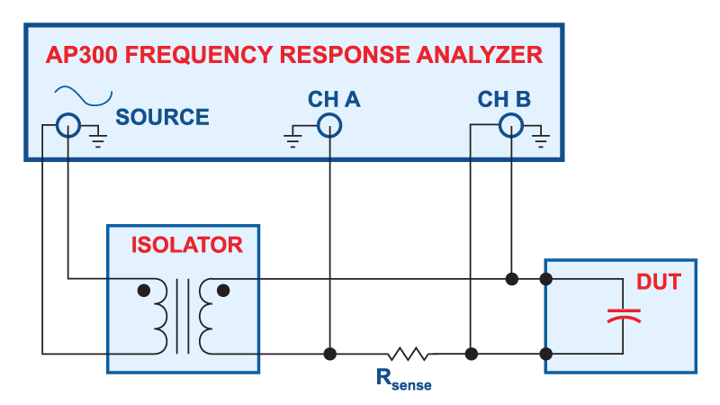
Figure 2: Measurement setup for low-impedance capacitors
Figure 2 shows how to make measurements of low-impedance capacitors with a frequency response analyzer [1]. Proper choice of sensing resistor, and proper RF layout of the test circuits will allow you to measure impedances as low as 1 mOhm with this test setup. While many component testers will only look at a single frequency, or a narrow range of frequencies, it is recommended that you sweep the frequency to see the impedance of the component under test from 10 Hz to at least 10 MHz.
Electrolytic Capacitor Measurement
Electrolytic capacitors are still the component of choice for most commercial, low-cost power supplies. They are also used extensively in automotive applications, where temperatures can be extreme.
Electrolytics are relatively easy to measure since they have relatively high equivalent series resistances. But it is important to vary the temperature of the capacitor to see its effect on the characteristics.
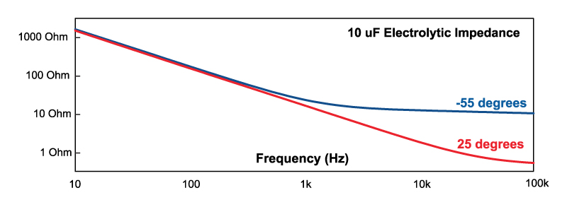
Figure 3: Impedance measurement of a 10 µF electrolytic capacitor at two different temperatures
Figure 3 shows the variation in capacitor impedance for a 10 uF electrolytic. Two curves are shown—the red plot is for the capacitor at 25 degrees, and the blue curve for -55 degrees Celcius. Notice the large separation in the curves. This is due to the well-known effect of electrolyte freezing in the capacitor. You will find in doing this measurement yourself that the ESR continues to rise as the temperature drops further and further below zero degrees. It is unlikely you will find the full set of data that you need for your particular part.
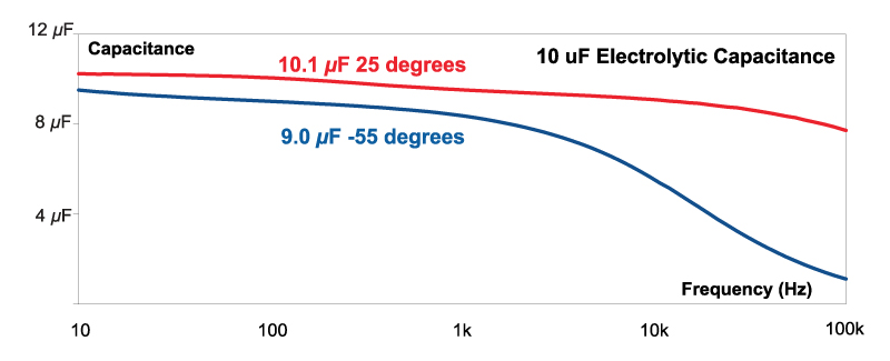
Figure 4: Capacitance of a 10 µF electrolytic capacitor at two different temperatures
Figure 4 shows the imaginary component of the impedance extracted to show the equivalent capacitor value. Two variations in capacitance are apparent—one is a weak dependence on frequency, and secondly, a dependence on temperature. For the cold capacitor of the blue curve, the apparent substantial drop in capacitance beyond a few kHz is not really significant since the impedance of the device is dominated by the equivalent series resistance (ESR) at those frequencies.
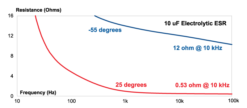
Figure 5: Equivalent series resistance of a 10 µF electrolytic capacitor at two different temperatures
The ESR is found by taking the real part of the impedance measurement of Figure 3, plotted in Figure 5. At low frequencies, both resistances measure high, but this is always a questionable measurement—we are trying to extract a very small real component from an impedance vector which is mostly reactive.
Beyond a few kHz, the ESR that we are concerned with is shown to be both frequency dependent, temperature-dependent. Notice that the cold capacitor has an ESR of about 12 ohms, while the warm capacitor is about 0.5 ohms. This is more than a 20:1 difference!
Many designers who operate over wide temperature ranges will stay away from electrolytics for this, and other, reasons. However, in some cases, they are economically necessary, and the control loop must accommodate the variations that will occur with temperature. This can present a significant challenge when designing the control loop. It can certainly be done, especially when using current mode control, but the loop bandwidth is often severely compromised.
Electrolytics will also vary substantially with aging, especially at elevated temperature. This is another involved topic which is beyond the scope of this article, but you must check the lifetime and temperature of operation in your power supply to ensure that the electrolytics are not going to fail.
Multilayer Ceramic Capacitor Measurement
Point-of-load power supplies, and motherboard supplies, have widely adopted multilayer ceramic capacitors as an alternate to electrolytics. Advances in construction techniques have made available very large value capacitors with extremely low ESRs, in very small packages. This is essential for point-of-load converters where board space is at a premium.
Rarely do I see due diligence done in considering the characteristics of MLC output capacitors. Even though they don’t suffer from the drastic temperature shifts of the ESR of electrolytics, MLCs are equally complex in their characteristics.
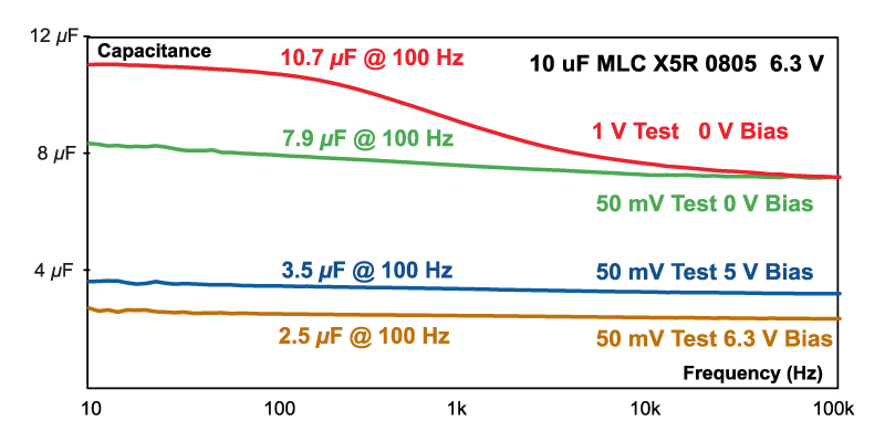
Figure 6: Measurement of a 10 µF multilayer ceramic capacitor at different test signal levels, and with varying DC bias
Figure 6 shows the capacitance value of a small 0805 MLC with a voltage rating of 6.3 V, and a nominal value of 10 µF. The red top curve shows that the capacitor has a value of 10.7 µF at 100 Hz. Notice the significant frequency dependence from 10 Hz to 10 kHz.
This change with frequency is due to the fact that the capacitance of an MLC is a function of the applied AC voltage [2]. In the test setup of Figure 2, a constant 1 V source is applied from the frequency response analyzer. At low frequencies, the voltage all appears across the capacitor, but as the frequency increases, the drive to the capacitor is reduced. MLCs show an increase in capacitance with drive level.
The green curve shows how this frequency dependence is eliminated with a small drive signal of just 50 mV. Notice that the value of the nominal 10 µF capacitor is now just 7.9 µF.
MLCs are also strongly dependent on the DC voltage which is applied. The blue curve of Figure 6 shows how the value of the capacitance drops to 3.5 µF with a 5 V DC bias, and to 2.5 µF with a 6.3 V DC bias. If you push the capacitor close to its voltage rating, you don’t have much capacitance left in this particular example. My experience with MLCs is that it’s not good to push them close to their rating anyway, for reliability reasons.
All of the different dielectrics used for MLCs will exhibit different characteristics. There is a lot of useful information on the AVX website, and you are encouraged to read as much as possible to understand this topic in depth. MLCs have additional dependence on temperature and lifetime which we won’t cover here.
While you can’t find a lot of information, it’s always a good idea to make measurements yourself on the bench. The MLC variations are so convoluted, that it is often hard to be sure exactly how your component will behave unless you measure it yourself. Also, most curves presented are typical characteristics, and many worst-case characteristics are so extreme that you can’t possible accommodate all of them in a practical design.
Summary
Capacitors are often overlooked as a source of variation in power supplies, but do not fall into this trap. All types of power supply capacitors have their own special sets of issues that you must thoroughly understand if you are going to build rugged converters.
Always make measurements of your power capacitors during the development phase. And, like inductors and cores for the magnetics, do not blindly make substitutions from one vendor or dielectric to another without proper characterization of the new part. Not all vendors do a good job of presenting full data—be prepared to do this yourself.
Additional Reading
[1] “Frequency Response Measurements”
[2] “High Voltage MLC Chips”, http://www.avx.com/docs/techinfo
[3] “Comparison of Multilayer Ceramic and Tantalum Capacitors”, http://www.avx.com/docs/techinfo