The Sepic converter dc analysis is presented, showing why this is a popular converter. Beware of the ac characteristics though.
Introduction
In the last article, we talked about the simplest of all converters, the buck converter, and showed how its control transfer functions could be extraordinarily complex. In this issue, we’ll go to the other end of the spectrum, and look at a converter that is far more complex, yet is often used by engineers who are unaware of the difficulties they may be in for.
Call this article, if you like, part II of “Power Supplies are Supposed to be Easy!”
The Sepic Converter
The most basic converter that we looked at last month is the buck converter. It is so named because it always steps down, or bucks, the input voltage. The output of the converter is given by
![]()
Interchange the input and the output of the buck converter, and you get the second basic converter – the boost. The boost always steps up, hence its name. The output voltage is always higher than the input voltage, and is given by:
![]()
What if you have an application where you need to both step up and step down sometimes, depending on the input and output voltage? Well, you could use two cascaded converters, one a buck and one a boost. Unfortunately that needs two separate controllers and switches. (It’s actually a good solution in many cases, and should not be rejected out of hand.)
The buck-boost converter has the desired step up and step down functions
![]()
but the output is inverted. A flyback converter (isolated buck-boost) requires a transformer instead of just an inductor, adding to the complexity of the development.
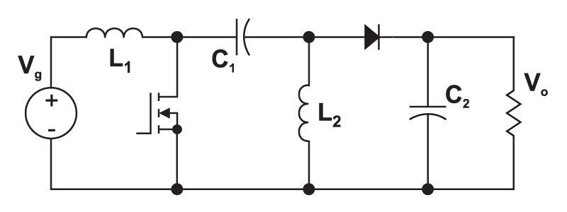
One converter that provides the needed input-to-output gain is the Sepic converter (single-ended primary inductor converter). This is shown in Fig. 1. It has become popular in recent years in battery-powered systems which must step up or down depending upon the charge level of the battery.
Figure 1: The Sepic converter can both step up and step down the input voltage, while maintaining the same polarity and the same ground reference for the input and output.
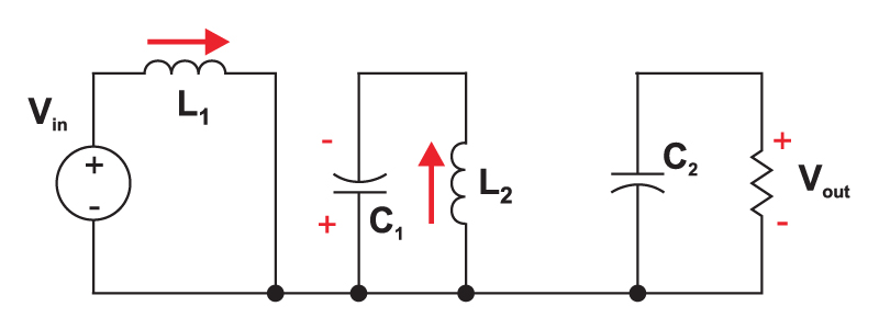
Fig. 2 shows the circuit when the power switch is turned on. The first inductor, L1, is charged from the input voltage source during this time. The second inductor takes energy from the first capacitor, and the output capacitor is left to provide the load current. The fact that both L1 and L2 are disconnected from the load when the switch is on leads to complex control characteristics, as we will see later.
Figure 2: When the switch is turned on, the input inductor is charged from the source, and the second inductor is charged from the first capacitor. No energy is supplied to the load capacitor during this time. Inductor current and capacitor voltage polarities are marked in this figure.
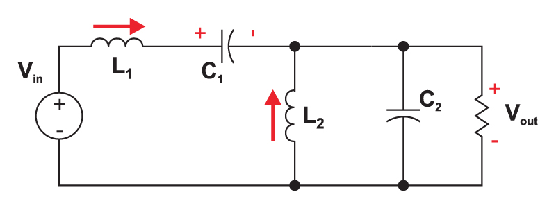
When the power switch is turned off, the first inductor charges the capacitor C1 and also provides current to the load, as shown in Fig. 3. The second inductor is also connected to the load during this time.
Figure 3: With the switch off, both inductors provide current to the load capacitor.
The output capacitor sees a pulse of current during the off time, making it inherently noisier than a buck converter. The input current is non-pulsating, a distinct advantage in running from a battery supply.
The PWM Switch Model in the Sepic Converter
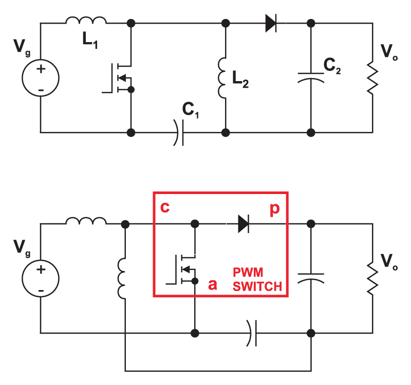
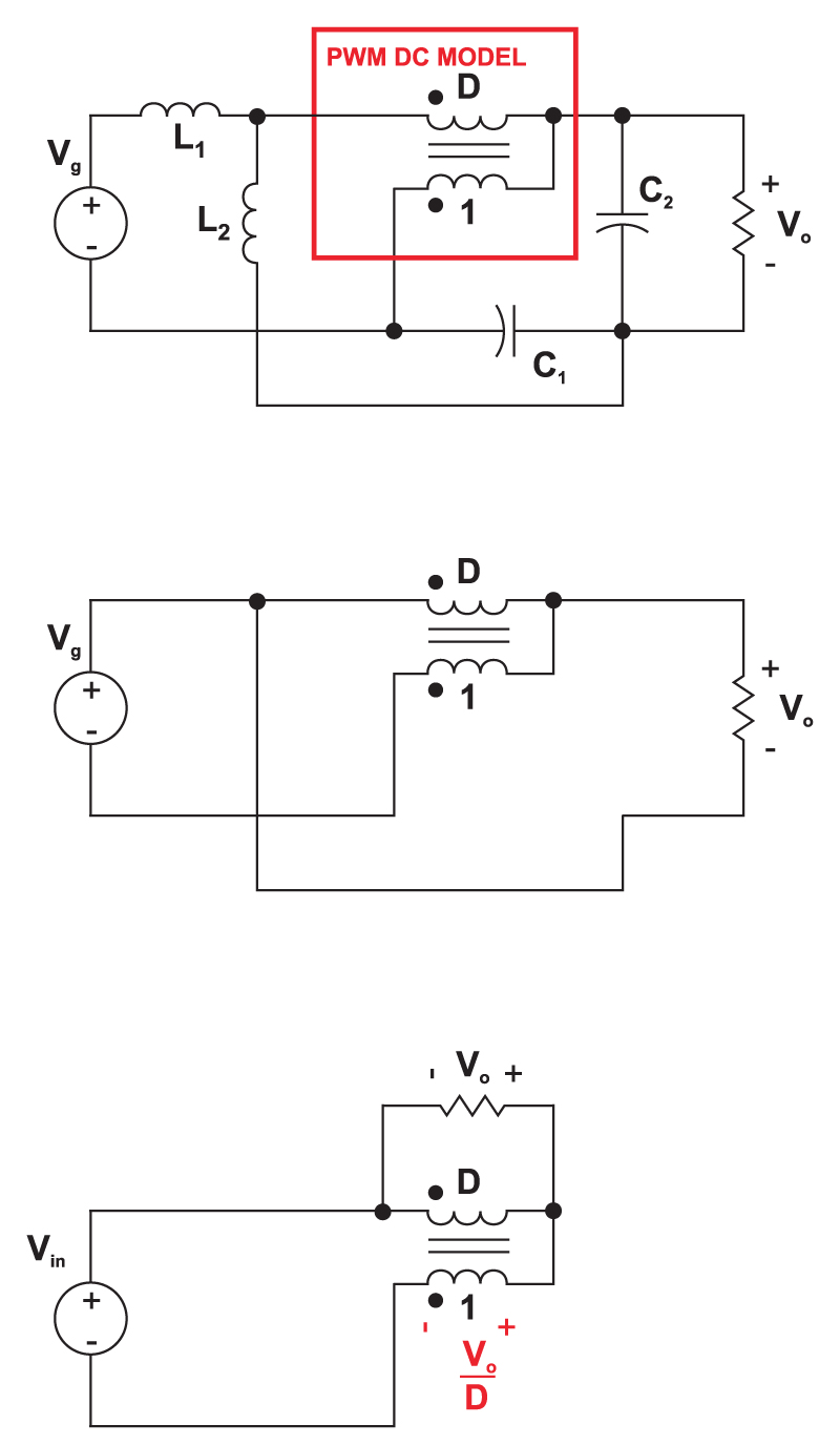
The best way to analyze both the DC and AC characteristics of the Sepic converter is by using the PWM switch model, developed by Vorpérian in 1986. Some minor circuit manipulations are first needed to reveal the location of the switch model, and this is shown in Fig. 4.
Figure 4: In order to take advantage of Vorpérian’s PWM switch model, the circuit elements must first be rearranged. The function of the original topology is retained when the capacitor is moved, and the second inductor is redrawn.
First, the capacitor C1 is moved to the bottom branch of the the converter. Then, inductor L2 is pulled over to the left, keeping its ends connected to the same nodes of the circuit. This reveals the PWM switch model of the converter, with its active, passive, and common ports, allowing us to use well-established analysis results for this converter.
For more background on the PWM switch model, the text book “Fast Analytical Techniques for Electrical and Electronic Circuits” [1] is high recommended.
DC Analysis of the Sepic Converter
Fig. 5 shows the equivalent circuit of the sepic converter with the dc portion of the PWM switch model in place. The dc model is just a 1:D transformer. We set the inductors of the circuit to be short circuits, and the capacitors to open circuits for the dc analysis. (You can, if you like, include any parasitic resistances in the model [2], but that’s beyond the scope of this article.)
Figure 5: For DC analysis, the small signal sources are set to zero, inductors become short circuits, and capacitors become open circuits. After the circuit is redrawn, it is a trivial matter to write KVL around the outer loop of the circuit to solve for the conversion gain of the converter.
After the circuit is manipulated as shown in the figure, we can write the KVL equation around the outer loop of the converter:
![]()
Rearranging gives:
![]()
And the DC gain is given by
![]()
Here we see the ability of the converter to step up or down, with a gain of 1 when D=0.5. Unlike the buck-boost and Cuk converters, the output is not inverted.
AC Analysis of the Sepic Converter
You won’t find a complete analysis of the Sepic converter anywhere in the printed literature. What you will find are application notes with comments like “the Sepic is not well-understood” but this hasn’t stopped engineers from using it.
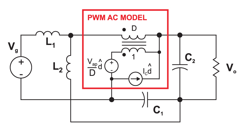
Figure 6: The small-signal ac sources are included in the switch model, and we can either solve the analysis by hand, or use PSpice to plot desired transfer functions. The hand analysis is crucial for symbolic expressions and design equations.
Proper small-signal analysis of the Sepic converter is a difficult analytical task, only made practical by advanced circuit analysis techniques originally developed by Middlebrook and continued by Vorpérian. [1].
If you’re going to build a Sepic, as a minimum, you need to understand the control characteristics. Fortunately, Vorpérian’s work is now available for this converter, and you can download the complete analysis notes from [2].
The simplified analysis of the Sepic converter, derived in detail in [2], ignores parasitic resistances of the inductors and capacitors, and yields the following result for the control-to-output transfer function:

Where


As you can see from these expressions, the “simplified” analysis is anything but simple. Including the parasitic resistances greatly complicates the analysis, but may be necessary for worst-case analysis of the Sepic converter. The analysis of this converter involves the use of the powerful extra element theorem, and Vorpérian’s book on circuit analysis techniques [1] is highly recommended to interested readers who want to explore this type of circuit analysis in more detail.
In addition to the inevitable fourth-order denominator of the Sepic, the most important features to note in the control transfer function are the terms in the numerator. The first term is a single right-half-plane (RHP) zero. Right-half-plane zeros are a result of converters where the response to an increased duty cycle is to initially decrease the output voltage.
When the power switch is turned on, the first inductor is disconnected from the load, and this directly gives rise to the first-order RHP zero. Notice that the expression only depends on the input inductor, L1, the load resistor, R, and the duty cycle.
The complex RHP zeros arise from the fact the turning on the switch disconnects the second inductor from the load. These zeros will actually move with the values of parasitic resistors in the circuit, so careful analysis of your converter is needed to ensure stability under all conditions.
PSpice Modeling of the Sepic Converter
The analytical solution above does not include all of the parasitic circuit elements. As you will see from [2], there is a prodigious amount of work to be done even without the resistances.
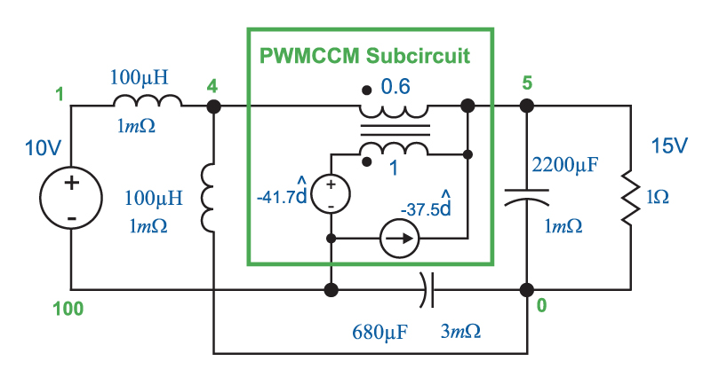
We can also use PSpice to help understand the Sepic better. Fig. 7 shows the circuit model for a specific numerical application of the Sepic, and it includes resistances which will affect the stability of the converter, sometimes in dramatic ways.
The PSpice file listing can be downloaded from [2] so you can reproduce these results to analyze your own Sepic converter.
Figure 7: Analysis can also be done with PSpice. This figure shows a specific design example for a 15 W converter. Parasitic resistances are included in the PSpice model
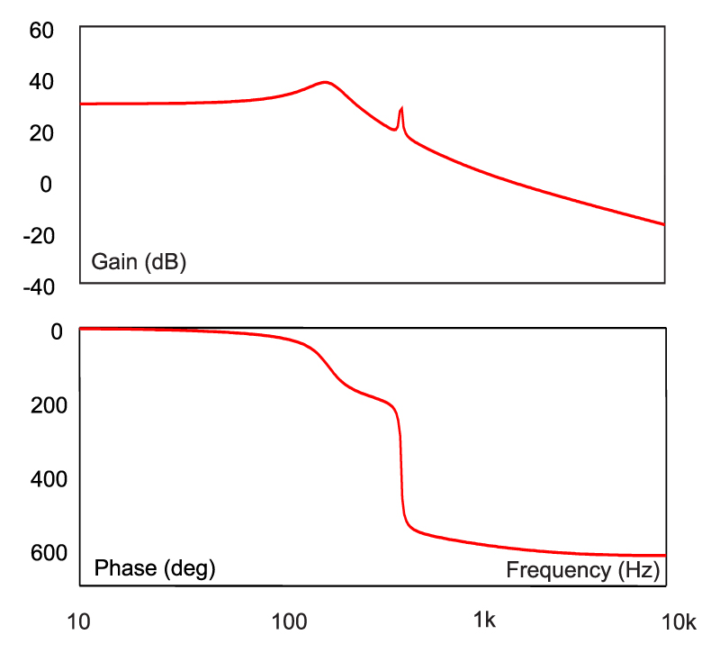
Fig. 8 shows the result of the PSpice analysis. The two resonant frequencies predicted by the hand analysis can clearly be seen in the transfer function plot. What is remarkable is the extreme amount of phase shift after the second resonance. This is caused by the delay of the second pair of poles, and the additional delay of the complex RHP zeros. The total phase delay through the converter is an astonishing 630 degrees. Controlling this converter at a frequency beyond the second resonance is impossible.
Figure 8: This shows the control-to-output transfer function for the Sepic converter. With low values of damping resistors, the converter has four poles, and three right-half-plane zeros. This results in an extreme phase delay of 630 degrees!
Summary
The Sepic converter definitely has some select applications where it is the topology of choice. How do designers get away with building such a converter? There are several possibilities. First, the dynamic and step load requirements on the system may be very benign, with no reason to design a loop with high bandwidth. This allows the loop gain to be reduced below 0 dB before the extreme phase delay of the second resonance.
Secondly, in many practical cases, the parasitic resistances of the circuit move the RHP zeros to the left half plane, greatly reducing the phase delay. This can also be done with the addition of damping networks to the power stage, a topic beyond the scope of this article.
Thirdly, some engineers do not build a regular Sepic. In some application notes, the two inductors are wound on the same core, often a toroid, which provides almost unity coupling between the two. In this case, the circuit no longer works as a regular Sepic, but this has become a very popular approach.
Additional Reading
- Join our LinkedIn group titled “Power Supply Design Center”. Noncommercial site with over 7000 helpful members with lots of theoretical and practical experience.
- For power supply hands-on training, please sign up for our workshops.
- [1] “Fast Analytical Techniques for Electrical and Electronic Circuits”, Vatché Vorpérian, Cambridge University Press 2002. ISBN 0 521 62442 8.


