How to measure and model high-frequency magnetics for switching power supplies. Essential steps for both custom-designed parts, or purchased components.
Power Supply Design Tips
This article points out some of the issues involved in designing, measuring, and modeling high-frequency magnetics for switching power supplies.
Despite efforts from some magnetics vendors to provide off-the-shelf components to power supply designers, almost all high-performance magnetics are custom. There are many deep and complex issues involved in the design of magnetics. I will try to cast some light on just a few of these issues.
Transformer Design Example
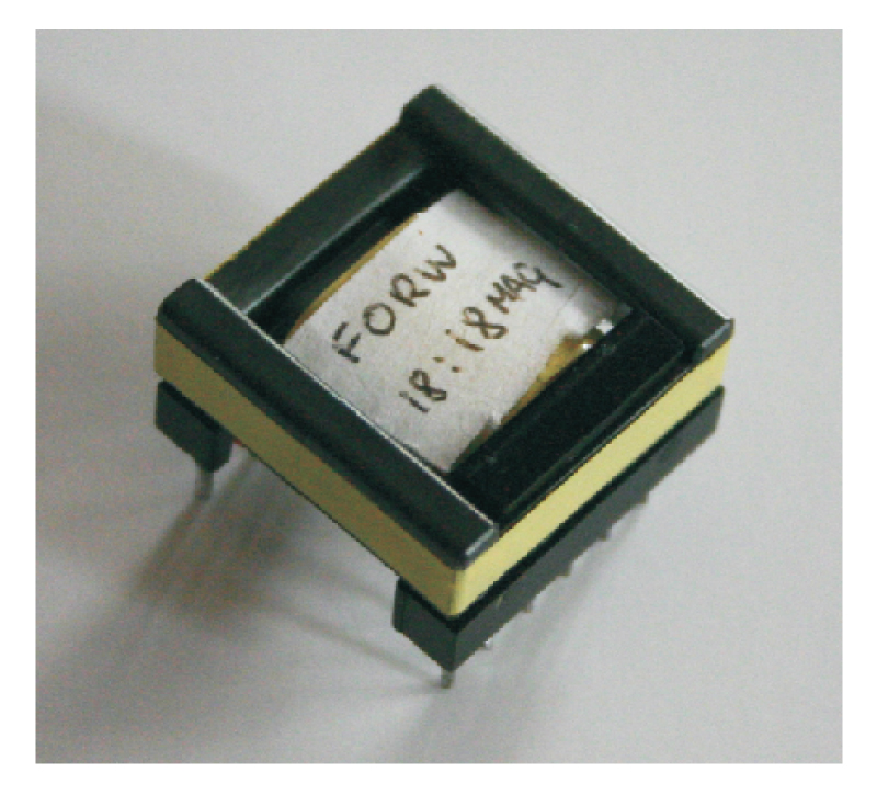
Figure 1 shows a simple 1:1 transformer. The transformer uses an ungapped EPC-25 core from TDK, made from PC-44 material. This transformer was designed for use in a 60 W forward converter with 36-60 V input and 12 V output.
Figure 1: A simple 1:1 transformer designed for a 100 kHz, 60 W forward converter.
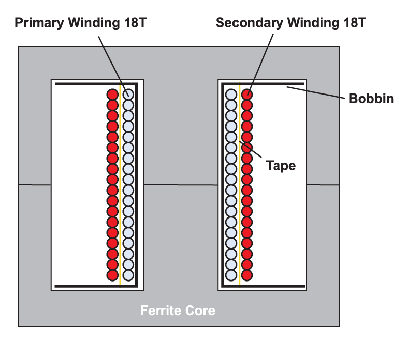
Figure 2 shows the winding layout, with just a single layer of 18 turns for the primary winding, a layer of thin insulation tape, and a single layer of 18 turns for the secondary winding.
Figure 2: Winding layout of the transformer of Figure 1.
This is a very straightforward, easy-to-manufacture design of a two-winding transformer. However, as you will see below, the resulting circuit element created is anything but simple.
Transformer Model
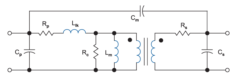
Figure 3 shows a commonly-used model for a two-winding transformer. On the primary side, the winding resistance is represented by Rp, the leakage inductance by Llk, magnetizing inductance by Lm, core loss by Rc, and self-capacitance by Cp.
The secondary winding resistance is Rs, the secondary self-capacitance is Cs, and the primary to secondary capacitance is Cm.
Figure 3: Equivalent circuit model used for 2-winding transformer.
The elements of this transformer model are used for several purposes—characterizing components, identifying problem design areas, and circuit simulation. However, this apparently simple model is complicated by the fact that all of the resistors and inductors of the model are nonlinear functions of either frequency, or excitation level, or both. The capacitors can also exhibit minor nonlinearities, but are further complicated by the fact that the lumped elements shown in Fig. 3 are a very crude approximation to the true multiple interwinding capacitance effects that really exist in the component.
Transformer Frequency Response Measurements
It is very useful to make frequency response measurements on a high-frequency power transformer, using a wide range of frequencies. For a two-winding transformer such as the example above, the most common measurements are impedance measurements from the primary side, with the secondary both open-circuited, and short-circuited.
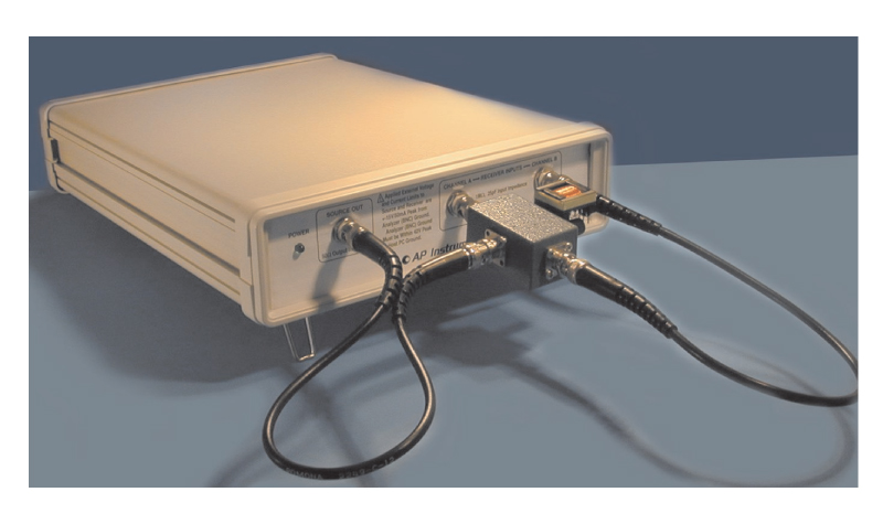
Figure 4: Impedance measurement test setup using the AP200 frequency response analyzer.
Fig. 4 shows a typical test setup for impedance measurements, using the AP200 frequency response analyzer. More detail of this test can be found in [1]. While many manufacturers only characterize their parts at a single frequency, we will see that it is important to measure characteristics over a very wide range in order to capture some of the important effects of the magnetic structure. For a 100 kHz transformer, important features show up in the measurement when it is swept from 1 Hz all the way to 15 MHz.
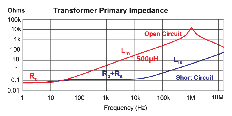
Figure 5: Primary impedance measurements with the secondary both open-circuited and short-circuited.
Fig. 5 shows the two impedance curves with the secondary open and short-circuited. The open-circuit measurement gives information on the primary resistance, magnetizing inductance, and capacitance (via the resonant frequency seen at about 1 MHz). The magnetizing inductance can vary significantly from one transformer to another due to material variations, temperature and frequency. However, for the sake of keeping this article short, the magnetizing inductance is treated as a constant over our frequency range of interest, and its value from the measured impedance is 500µH.
Core loss is a quantity that we will also not consider in detail in this article due to the complexity of the topic. The reader is encouraged to refer to [2,3] for more information on advanced modeling and measurement of core losses.
Leakage Inductance
The short-circuit measurement of Fig. 5 contains a wealth of useful information which will strongly affect the performance of the transformer. At very low frequencies (below 5Hz) we can directly measure the primary dc resistance. Beyond 10Hz, we see the value of the primary and reflected secondary resistance.
At frequencies above 10 kHz, the impedance rises due to an increase in resistance, and the leakage inductor impedance. From the impedance curve, we need to separate out the real and imaginary parts to establish the contribution of each of these elements.
Figure 6: Leakage inductance calculated automatically from the transformer short-circuit impedance measurement.
Fig. 6 shows the imaginary component extracted from the short-circuit impedance measurement, used to calculate the value of the leakage inductance. This is a very interesting curve in that it does not produce a fixed value of leakage inductance versus frequencies as many engineers would expect.
Below 5 kHz, the reactive component of the short-circuit measurement is small compared to the total impedance, and accuracy of measurement is lost at these lower frequencies.
Above 40 kHz, the inductance starts to decrease significantly from just above 0.8 µH to 0.4 µH above 10 MHz. The change in inductance is due to proximity effects in the windings. At high frequencies, the current in the primary and secondary are not distributed evenly through the wire. In fact, they move closer to the surface of the wire at the isolation boundary between the winding layers. This drops the leakage inductance.
This leads to the interesting question—which value to use? The leakage inductance will cause ringing in the circuit at high frequencies, so it is essential to know the value at the ringing frequency in order to be able to design a proper snubber. However, for production design verification, you might want to use the fixed value between 5 kHz and 40 kHz as a specification to the manufacturer, but you must specify the measurement frequency if you want the parts built with good tolerance.
There is an industry rule of thumb that I often see quoted: “The leakage inductance should be 1% of magnetizing inductance for a transformer.” In our design example, the leakage is less than 0.2% of magnetizing inductance at 10 kHz, and 0.1% at 10 MHz. Never accept the 1% figure from a manufacturer as a design objective. Make the best transformer you can with tightly coupled windings, measure your prototype, and expect the manufacturer to match it closely.
Measured Winding Resistance
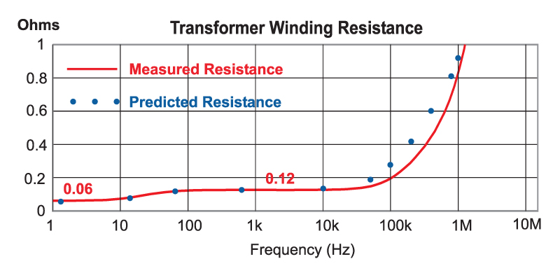
Fig. 7 shows the real component extracted from the short-circuit impedance measurement, used to calculate the value of the winding resistance.
Figure 7: Transformer winding resistance found by extracting the real component of the short-circuit primary impedance measurement.
Proximity effects in the windings affect the resistance even more than the inductance, and the increase in loss at high frequencies can be very severe. The DC resistance of the primary and secondary wires in series is 0.12 ohms, as shown in the curve up to about 10 kHz. Beyond this, the resistance rises steeply, and at 1 MHz, the resistance of the wire is about 7-8 times higher than the DC resistance. At 100 kHz, the switching frequency of the converter, the wire resistance is almost double its DC value.
This increase in AC resistance will directly affect the losses in the transformer, and it is crucial to quantify this before settling on a transformer (or inductor) design. You can even estimate this effect before building the transformer, and this is shown in Fig. 7 by the blue dots. Calculations are done using a form of Dowell’s equation and you can read more about this in [4].
Summary
When designing transformers and inductors, you should always be aware that these seemingly simple structures are in fact very complex electromagnetic devices. Linear circuit models are a very crude approximation to the real component, and most of the elements of the circuit models have strong nonlinearities in them. For this reason, you can only expect very limited results in trying to run circuit simulators on power supplies.
You should always make extended frequency response measurements on transformers when you are developing components. This will show increase in resistance with frequency, and change in leakage inductance, allowing you to properly specify the test conditions for a tightly-controlled part.
The changes in the winding resistance and leakage inductance will be strongly dependent upon the physical winding layouts of the transformer, and great care should be taken to control this as tightly as possible during design and manufacturing.
Additional Reading
- Join our LinkedIn group titled “Power Supply Design Center”. Noncommercial site with over 7000 helpful members with lots of theoretical and practical experience.
- For power supply hands-on training, please sign up for our workshops.
- “Measuring Frequency Response”, Ray Ridley
- “Core Loss Modeling and Measurement”, Chris Oliver, Micrometals
- “Modeling Ferrite Core Losses”, Ray Ridley


