


Proximity Loss in Magnetics Windings
Exploring the use of custom versus off-the-shelf magnetics design. Standard parts are designed to a price point, and must be tested properly if you want to use them.
Power Supply Design Tips
In this article, we continue the theme of custom versus off-the-shelf magnetics design. The relatively simple output inductor of a forward converter is used as an example to show the issues and pitfalls involved in trying to use off-the-shelf inductor designs for high-frequency power supply applications.
Power Inductor Design
When I first started my career in power electronics, over 25 years ago, all magnetic components were custom designed and manufactured. In our current power supply design workshops, we dedicate an entire day to the theory and practice of making custom inductors for switching power supplies. Attendees at the course design, analyze, and build their own inductors and transformers in the lab.[1]
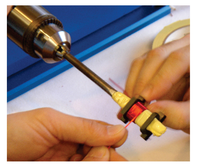
Figure 1: Building custom magnetics in our design workshop.
In the last few years, numerous companies have developed kits of standard parts aimed at the semiconductor companies to integrate into their designs. This proliferation of parts has recently led me to wonder if custom inductor design was becoming a skill belonging more to the past than the future.
Figure 2 shows two inductor designs, one developed in our workshop for a rugged 60-W converter, and the smaller low-cost, off-the-shelf part. You can see a significant size advantage of the standard component.
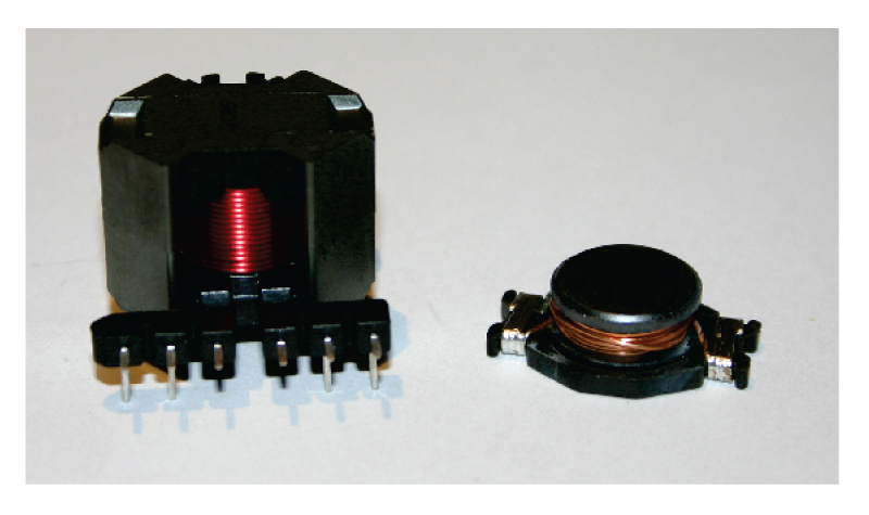
Figure 2: (a) 47 µH custom inductor and (b) off-the-shelf commodity component
The 47 µH custom inductor was designed to operate continuously at 5 A, with plenty of margin for overcurrent situations.
The off-the-shelf inductor, also 47 µH, had a single number assigned to it on the parts kit—a current rating of 5 A. Since the parts kit is aimed at the non-experienced power supply designer, it seems reasonable to assume that the inductor is suitable for a 5 A converter application
The parts are quite different in their design, as shown in Fig. 3. The custom-made inductor has a single-layer winding on an RM8 core, with a gapped center leg. The windings are a significant distance away from the center leg gap, essential to avoid proximity losses in the windings at high frequencies.
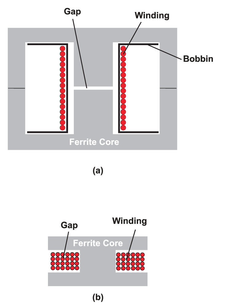
Figure 3: Cross-section of (a) RM8 core and (b) drum core showing winding layouts.
The off-the-shelf part is very different—a small drum-shaped core with many turns wound on the core in multiple layers. The air gap is large, and the windings are all situated in the middle of the gap. This violates all the rules of high-frequency inductor design as I know them, but it’s hard to argue with the size, cost, and current rating of the part compared to a custom design.
Forward Converter Testing
So how do these parts compare? Each was inserted into the forward converter shown in Fig. 4, and run at 4.5 A. Initially, the waveforms for the two parts look the same, as shown in Fig. 5(a).
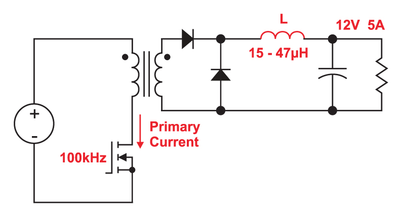
Figure 4: Forward converter schematic. Output is 12 V, 5 A, switching at 100 kHz. The reset circuit of the transformer is omitted for simplicity.
However, after 30 seconds of operation, the drum core design became very hot. The primary current started showing curvature, shown in 5(b), indicating the onset of saturation of the core material. The inductor temperature quickly rose further, shown in 5( c). Testing was stopped after the waveform of Figure 5( d) showed complete saturation, and smoke started coming out of the windings.
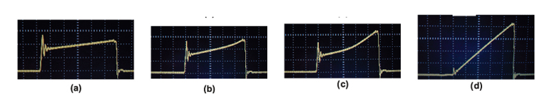
Figure 5: Primary switch current waveforms for a forward converter with a 47µH inductor: (a) proper operation with RM8 custom design, (b) drum core after 30 seconds at room temperature ambient, (c) drum core after 60 seconds, (d) drum core after 3 minutes operation.
Clearly, the rating of 5 A, listed on the parts package, was not accurate. As a power engineer, knowing that a 5 A rating could have many meanings, I referred to the data sheet on the manufacturer’s website, and found that this current referred to saturation current, not continuous current. The continuous dc current rating was only 2.8 A.
The next experiment used a 15 µH part, with a stated current rating of 9 A. This was also a saturation current, and the continuous dc current was listed as 5 A. The waveforms of Fig. 6 show the results.
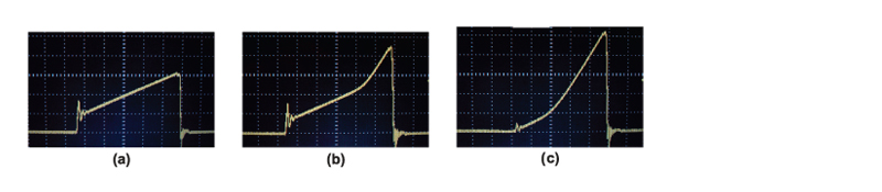
Figure 6: Primary switch current waveforms for a forward converter with a 15µH off-the-shelf drum core inductor: (a) initial operation, (b) after 60 seconds at room temperature ambient, (c) after 3 minutes operation.
Once again, the inductor started out fine with a 4.5 A load, but began to saturate after 1 minute of operation. In this case, the dc current rating should have been sufficient, but another level of analysis is needed—the inductor design is inadequate for the high frequency ac current imposed upon it, and for this there was no proper specification provided.
Inductor AC Resistance Measurements
The problem of the smaller inductor is clearly illustrated by measuring the frequency dependence of the resistance of the inductor windings. Fig. 7 shows how this resistance changes up to 1 MHz for both the drum core, and the RM8 design.
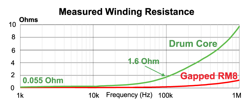
Figure 7: Measured winding resistance of a custom RM8 inductor design, and an off-the-shelf drum-core design.
The dc resistance of the windings for both designs was approximately 55 mOhms. However, at 100 kHz, this rises to 1.6 Ohms for the drum core, and to 100 mOhms for the RM8 core design. In other words, while the dc resistance and inductance of the parts are the same, the resistance of the small off-the-shelf part is ten times higher at 100 kHz.
The rapid rise of resistance of the drum core design is due to the proximity loss with the multiple layers of windings located in the gap area of the core. [2]. The inductor is basically unusable with any appreciable amount of ripple current at the switching frequency.
Summary
By all means take a look at standard off-the-shelf parts when designing power inductors,. Be aware, however, that the apparent ratings may greatly overstate the capabilities of the part in your application. You need to dig deep into the data sheets to find out whether that part is truly acceptable in your circuit. If the inductor looks far smaller that you anticipated, it’s probably inadequate for the job.
In a rugged power supply, you should never, under any conditions of line, load, and temperature, and transients, see curved waveforms like those shown in this article. Those waveforms indicate failure of the magnetic core material, and will lead to breakdown of the winding insulation, or semiconductor failure.
And finally, if you need the best inductor for your application—go ahead and design it properly yourself. Off-the-shelf parts are optimized for cost in high volume applications, and will rarely be the best solution for your circuit.
Additional Reading
- Join our LinkedIn group titled “Power Supply Design Center”. Noncommercial site with over 7000 helpful members with lots of theoretical and practical experience.
- For power supply hands-on training, please sign up for our workshops.
- “Proximity Loss in Magnetics Windings”, Ray Ridley